Cirkit Designer Logo
Cirkit Designer
Your all-in-one circuit design IDE
Home / 
Component Documentation

How to Use nodemcu8266 lolin basboard: Examples, Pinouts, and Specs

Image of nodemcu8266 lolin basboard
Cirkit Designer LogoDesign with nodemcu8266 lolin basboard in Cirkit Designer

Introduction

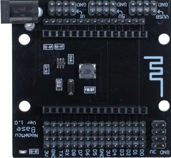
The NodeMCU8266 Lolin Baseboard, manufactured by ESP, is a development board based on the ESP8266 Wi-Fi module. It is designed for IoT (Internet of Things) applications, offering a compact and versatile platform for wireless connectivity. The board integrates a USB-to-serial interface, making it easy to program and debug. It is widely used for prototyping smart home devices, wireless sensors, and other IoT projects.

Explore Projects Built with nodemcu8266 lolin basboard

Use Cirkit Designer to design, explore, and prototype these projects online. Some projects support real-time simulation. Click "Open Project" to start designing instantly!
WiFi-Controlled Basket-Carrying Robot with GPS and GSM Notification
Image of trash collecting vessel: A project utilizing nodemcu8266 lolin basboard in a practical application
This circuit is designed for a 4-wheeled WiFi-controlled car with a basket, which uses an ESP8266 NodeMCU microcontroller for logic control. It features an IR sensor for basket full detection, a GPS module for location tracking, and a GSM module (Sim800l) for sending SMS notifications. The L298N motor driver controls four DC gearmotors for movement, and the system is powered by a Li-ion battery with a 7805 voltage regulator providing stable power to the GSM module.
Cirkit Designer LogoOpen Project in Cirkit Designer
ESP8266 NodeMCU Wi-Fi Enabled OLED Display with RYLR896 Communication Module
Image of Smart Irrigation system Rx Side: A project utilizing nodemcu8266 lolin basboard in a practical application
This circuit features an ESP8266 NodeMCU microcontroller connected to a 0.96" OLED display and an RYLR896 LoRa module. The ESP8266 communicates with the OLED via I2C protocol and interfaces with the LoRa module using UART, enabling wireless data transmission and display capabilities.
Cirkit Designer LogoOpen Project in Cirkit Designer
ESP8266 NodeMCU Controlled Environment Monitoring System with Stepper Motor and Sensors
Image of Smart Window Blind System: A project utilizing nodemcu8266 lolin basboard in a practical application
This circuit features an ESP8266 NodeMCU microcontroller connected to a ULN2003A breakout board to drive a 28BYJ-48 stepper motor. The ESP8266 also interfaces with a DHT11 temperature and humidity sensor and an LDR (light-dependent resistor) module for environmental sensing. Power is supplied by a 5V DC source, which is distributed to the motor driver, sensors, and the microcontroller.
Cirkit Designer LogoOpen Project in Cirkit Designer
ESP8266 and SIM800L Based GPS Tracker with I2C LCD Display and Battery Power
Image of Little Innovator Competition: A project utilizing nodemcu8266 lolin basboard in a practical application
This circuit integrates an ESP8266 NodeMCU microcontroller with a SIM800L GSM module, a GPS NEO 6M module, and a 16x2 I2C LCD display for communication and location tracking. It also includes a pushbutton for user input, a piezo buzzer for audio alerts, and is powered by a 2x 18650 battery pack through an LM2596 step-down module.
Cirkit Designer LogoOpen Project in Cirkit Designer

Explore Projects Built with nodemcu8266 lolin basboard

Use Cirkit Designer to design, explore, and prototype these projects online. Some projects support real-time simulation. Click "Open Project" to start designing instantly!
Image of trash collecting vessel: A project utilizing nodemcu8266 lolin basboard in a practical application
WiFi-Controlled Basket-Carrying Robot with GPS and GSM Notification
This circuit is designed for a 4-wheeled WiFi-controlled car with a basket, which uses an ESP8266 NodeMCU microcontroller for logic control. It features an IR sensor for basket full detection, a GPS module for location tracking, and a GSM module (Sim800l) for sending SMS notifications. The L298N motor driver controls four DC gearmotors for movement, and the system is powered by a Li-ion battery with a 7805 voltage regulator providing stable power to the GSM module.
Cirkit Designer LogoOpen Project in Cirkit Designer
Image of Smart Irrigation system Rx Side: A project utilizing nodemcu8266 lolin basboard in a practical application
ESP8266 NodeMCU Wi-Fi Enabled OLED Display with RYLR896 Communication Module
This circuit features an ESP8266 NodeMCU microcontroller connected to a 0.96" OLED display and an RYLR896 LoRa module. The ESP8266 communicates with the OLED via I2C protocol and interfaces with the LoRa module using UART, enabling wireless data transmission and display capabilities.
Cirkit Designer LogoOpen Project in Cirkit Designer
Image of Smart Window Blind System: A project utilizing nodemcu8266 lolin basboard in a practical application
ESP8266 NodeMCU Controlled Environment Monitoring System with Stepper Motor and Sensors
This circuit features an ESP8266 NodeMCU microcontroller connected to a ULN2003A breakout board to drive a 28BYJ-48 stepper motor. The ESP8266 also interfaces with a DHT11 temperature and humidity sensor and an LDR (light-dependent resistor) module for environmental sensing. Power is supplied by a 5V DC source, which is distributed to the motor driver, sensors, and the microcontroller.
Cirkit Designer LogoOpen Project in Cirkit Designer
Image of Little Innovator Competition: A project utilizing nodemcu8266 lolin basboard in a practical application
ESP8266 and SIM800L Based GPS Tracker with I2C LCD Display and Battery Power
This circuit integrates an ESP8266 NodeMCU microcontroller with a SIM800L GSM module, a GPS NEO 6M module, and a 16x2 I2C LCD display for communication and location tracking. It also includes a pushbutton for user input, a piezo buzzer for audio alerts, and is powered by a 2x 18650 battery pack through an LM2596 step-down module.
Cirkit Designer LogoOpen Project in Cirkit Designer

Common Applications and Use Cases

  • Home automation systems
  • Wireless data logging
  • IoT-enabled appliances
  • Remote monitoring and control
  • Prototyping Wi-Fi-enabled devices

Technical Specifications

Key Technical Details

  • Microcontroller: ESP8266
  • Operating Voltage: 3.3V
  • Input Voltage (via USB): 5V
  • Digital I/O Pins: 11
  • Analog Input Pins: 1 (10-bit ADC)
  • Flash Memory: 4MB
  • Wi-Fi Standard: 802.11 b/g/n
  • USB Interface: CH340G USB-to-serial converter
  • Dimensions: 58mm x 31mm

Pin Configuration and Descriptions

The NodeMCU8266 Lolin Baseboard has a total of 30 pins. Below is the pinout description:

Pin Name Type Description
VIN Power Input External power input (5V).
3V3 Power Output 3.3V output from the onboard regulator.
GND Ground Ground connection.
D0-D8 Digital I/O General-purpose digital input/output pins.
A0 Analog Input Analog input pin (0-1V range).
TX UART TX Transmit pin for serial communication.
RX UART RX Receive pin for serial communication.
EN Enable Chip enable pin. Active high to enable the module.
RST Reset Resets the microcontroller when pulled low.
GPIO16 Wake-up Pin Can be used for deep sleep wake-up.

Usage Instructions

How to Use the Component in a Circuit

  1. Powering the Board:

    • Connect the board to your computer via a micro-USB cable for power and programming.
    • Alternatively, supply 5V to the VIN pin and GND for external power.
  2. Programming the Board:

    • Install the Arduino IDE and add the ESP8266 board package via the Board Manager.
    • Select "NodeMCU 1.0 (ESP-12E Module)" as the board type.
    • Connect the board to your computer and select the appropriate COM port.
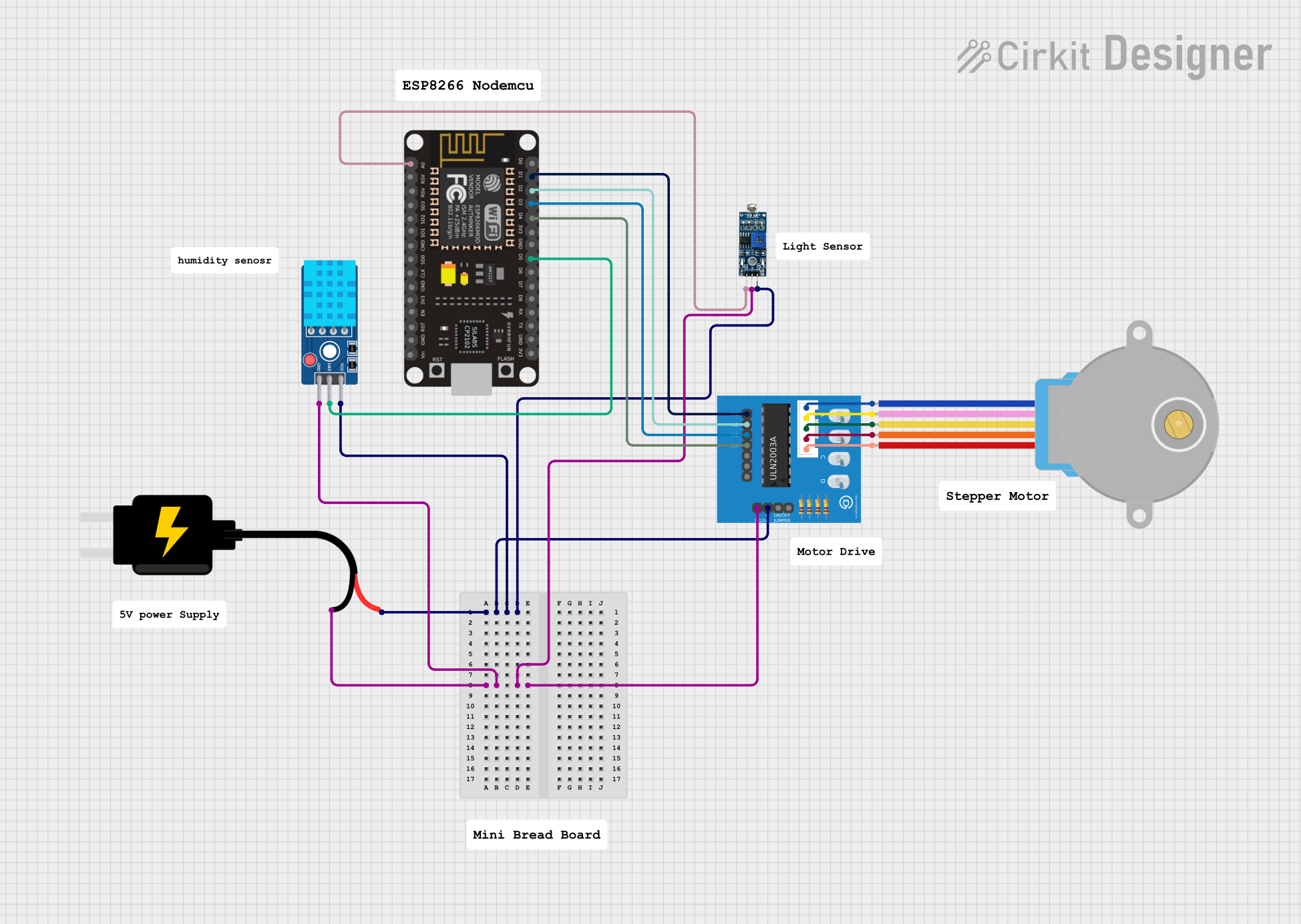
  3. Connecting Peripherals:

    • Use the digital pins (D0-D8) for connecting sensors, actuators, or other devices.
    • Use the A0 pin for analog sensors (ensure the input voltage does not exceed 1V).

Important Considerations and Best Practices

  • Voltage Levels: The GPIO pins operate at 3.3V. Avoid applying 5V directly to the pins to prevent damage.
  • Wi-Fi Antenna: Ensure the onboard antenna is not obstructed for optimal Wi-Fi performance.
  • Deep Sleep Mode: Use GPIO16 to wake the board from deep sleep for low-power applications.
  • Pull-up Resistors: Some pins (e.g., D3, D4) have internal pull-up resistors. Be cautious when connecting external components.

Example Code for Arduino IDE

Below is an example code to connect the NodeMCU8266 Lolin Baseboard to a Wi-Fi network and print the IP address:

#include <ESP8266WiFi.h> // Include the ESP8266 Wi-Fi library

const char* ssid = "Your_SSID";       // Replace with your Wi-Fi network name
const char* password = "Your_Password"; // Replace with your Wi-Fi password

void setup() {
  Serial.begin(115200); // Initialize serial communication at 115200 baud
  delay(10);

  Serial.println(); 
  Serial.println("Connecting to Wi-Fi...");

  WiFi.begin(ssid, password); // Start Wi-Fi connection

  while (WiFi.status() != WL_CONNECTED) {
    delay(500); // Wait for connection
    Serial.print(".");
  }

  Serial.println();
  Serial.println("Wi-Fi connected!");
  Serial.print("IP Address: ");
  Serial.println(WiFi.localIP()); // Print the assigned IP address
}

void loop() {
  // Add your main code here
}

Troubleshooting and FAQs

Common Issues and Solutions

  1. Board Not Detected by Computer:

    • Ensure the USB cable is functional and supports data transfer.
    • Install the CH340G driver if the board is not recognized.
  2. Wi-Fi Connection Fails:

    • Double-check the SSID and password.
    • Ensure the Wi-Fi network is within range and not using unsupported security protocols.
  3. Upload Errors in Arduino IDE:

    • Select the correct board and COM port in the Arduino IDE.
    • Press and hold the "Flash" button on the board while uploading the code.
  4. Analog Readings Are Inaccurate:

    • Ensure the input voltage to the A0 pin is within the 0-1V range. Use a voltage divider if necessary.

FAQs

  • Q: Can I power the board with a battery?
    A: Yes, you can use a 3.7V LiPo battery connected to the VIN and GND pins.

  • Q: What is the maximum current output of the 3V3 pin?
    A: The 3V3 pin can supply up to 500mA, depending on the input power source.

  • Q: Can I use the board without Wi-Fi?
    A: Yes, the board can function as a standalone microcontroller without using Wi-Fi.

  • Q: How do I reset the board?
    A: Press the "RST" button or pull the RST pin low to reset the board.

This documentation provides a comprehensive guide to using the NodeMCU8266 Lolin Baseboard effectively. For further assistance, refer to the official ESP documentation or community forums.