How to Use Parallax Gps: Examples, Pinouts, and Specs
Introduction
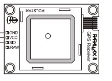
The Parallax GPS module (part number 28146) is a compact, high-performance GPS receiver with a serial interface that can provide precise geographic location information. Utilizing Global Positioning System (GPS) technology, this module is capable of tracking up to 12 satellites to determine its position, velocity, and time data. Common applications include navigation systems, time synchronization, asset tracking, and location-based services.
Explore Projects Built with Parallax Gps
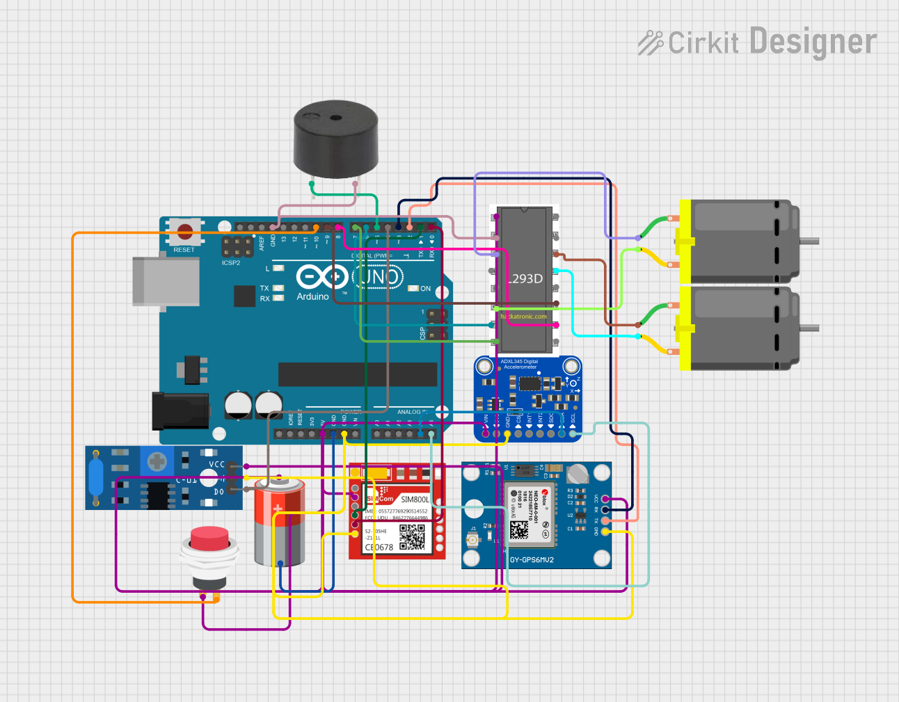

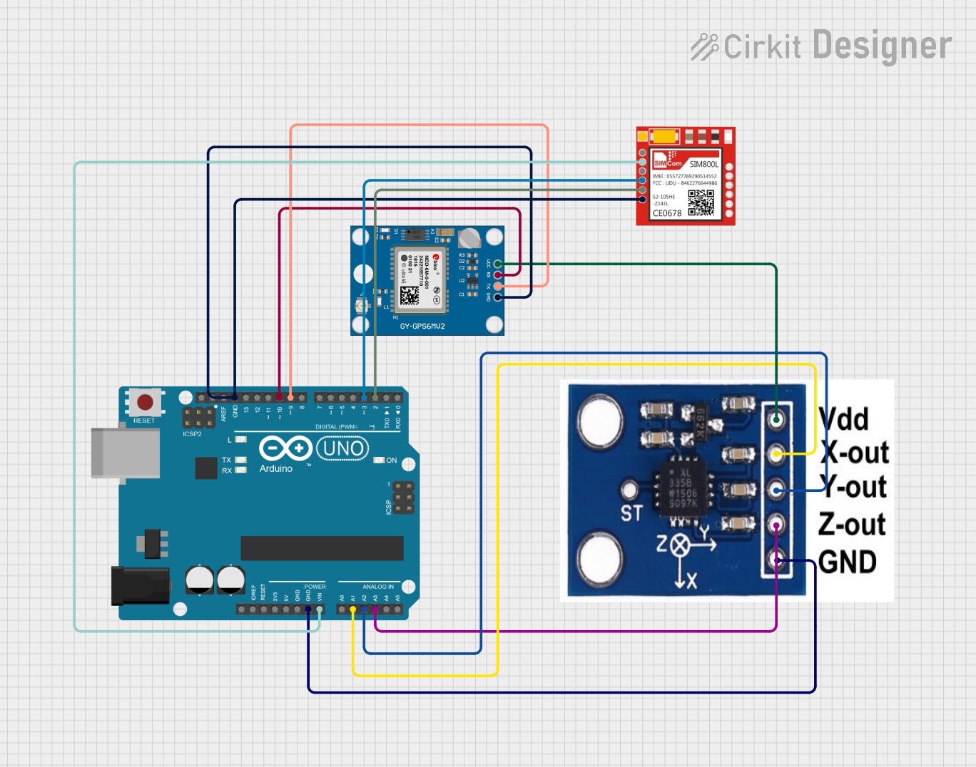

Explore Projects Built with Parallax Gps
Technical Specifications
Key Technical Details
- Receiver Type: 12 parallel channel GPS receiver
- Update Rate: 1 Hz (once per second)
- Communication Interface: Serial (4800 bps default)
- Antenna: Built-in patch antenna
- Supply Voltage: 3.0 to 3.3 VDC
- Operating Current: 75 mA (typical)
- Time to First Fix: 45 seconds (cold start), 38 seconds (warm start)
- Sensitivity: -159 dBm tracking, -142 dBm acquisition
- Operating Temperature: -40°C to +85°C
Pin Configuration and Descriptions
| Pin Number | Name | Description |
|---|---|---|
| 1 | VCC | Power supply input (3.0 to 3.3 VDC) |
| 2 | TX | Transmit data out (TTL level) |
| 3 | RX | Receive data in (TTL level) |
| 4 | GND | Ground connection |
Usage Instructions
Connecting to a Circuit
To use the Parallax GPS module in a circuit, connect the VCC pin to a 3.0 to 3.3 VDC power source, the GND pin to the ground, and the TX and RX pins to the respective receive and transmit pins of your microcontroller or serial adapter.
Best Practices
- Ensure that the GPS module has a clear view of the sky for optimal satellite reception.
- Avoid placing the module near devices that emit RF noise, as this can interfere with GPS signal reception.
- Use proper ESD precautions when handling the GPS module to prevent damage to the sensitive electronics.
Example Code for Arduino UNO
#include <SoftwareSerial.h>

// Create a software serial port called "gpsSerial" on pins 3 and 4
SoftwareSerial gpsSerial(3, 4); // RX, TX

void setup() {
  // Start the Arduino hardware serial port at 9600 bps
  Serial.begin(9600);
  // Start the software serial port at 4800 bps
  gpsSerial.begin(4800);
}

void loop() {
  // Check if data is available on the GPS serial port
  if (gpsSerial.available()) {
    // Read the incoming byte from the GPS module
    char gpsData = gpsSerial.read();
    // Send the byte to the Arduino hardware serial port
    Serial.write(gpsData);
  }
}
This example code sets up a software serial port on the Arduino UNO to communicate with the Parallax GPS module. The GPS module's TX pin is connected to pin 3 on the Arduino (software serial RX), and the GPS module's RX pin is not used in this example. The Arduino's hardware serial port is used to output the GPS data to the Serial Monitor.
Troubleshooting and FAQs
Common Issues
- No Data Output: Ensure that the GPS module's TX pin is correctly connected to the microcontroller's RX pin. Check that the power supply is within the specified voltage range and that the module has a clear view of the sky.
- Intermittent Signal: Make sure there are no obstructions such as buildings or trees blocking the view of the sky. Also, check for sources of RF interference nearby.
Solutions and Tips
- Cold Start: If the GPS module is taking longer than expected to acquire a signal, it may be experiencing a cold start. Place the module in an open area with a clear view of the sky and wait for a few minutes.
- Data Parsing: The data output from the GPS module is in NMEA format. You will need to parse this data to extract useful information such as latitude, longitude, and time.
FAQs
Q: How can I increase the update rate of the GPS module? A: The update rate is fixed at 1 Hz and cannot be changed for this module.
Q: Can I use the GPS module indoors? A: GPS signals are weak and typically require a clear line of sight to the sky. Indoor use is not recommended and may result in poor performance.
Q: What is the accuracy of the Parallax GPS module? A: The accuracy of the module is dependent on several factors, including satellite geometry and atmospheric conditions. Under ideal conditions, the accuracy is typically within 5 to 10 meters.
For further assistance, please refer to the Parallax GPS module datasheet or contact technical support.