How to Use Arduino Uno R3: Examples, Pinouts, and Specs
Introduction
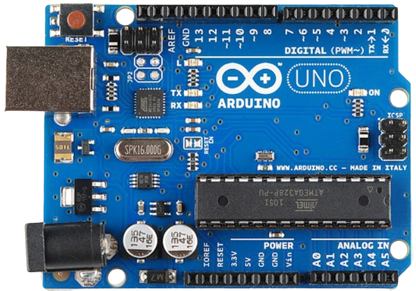
The Arduino Uno R3 is a microcontroller board based on the ATmega328P. It is designed to be an easy-to-use platform for creating interactive projects. The board features 14 digital input/output pins, 6 analog inputs, a 16 MHz quartz crystal, a USB connection, a power jack, an ICSP header, and a reset button. The Arduino Uno R3 is widely used in various applications, including prototyping, educational projects, and hobbyist electronics.
Explore Projects Built with Arduino Uno R3
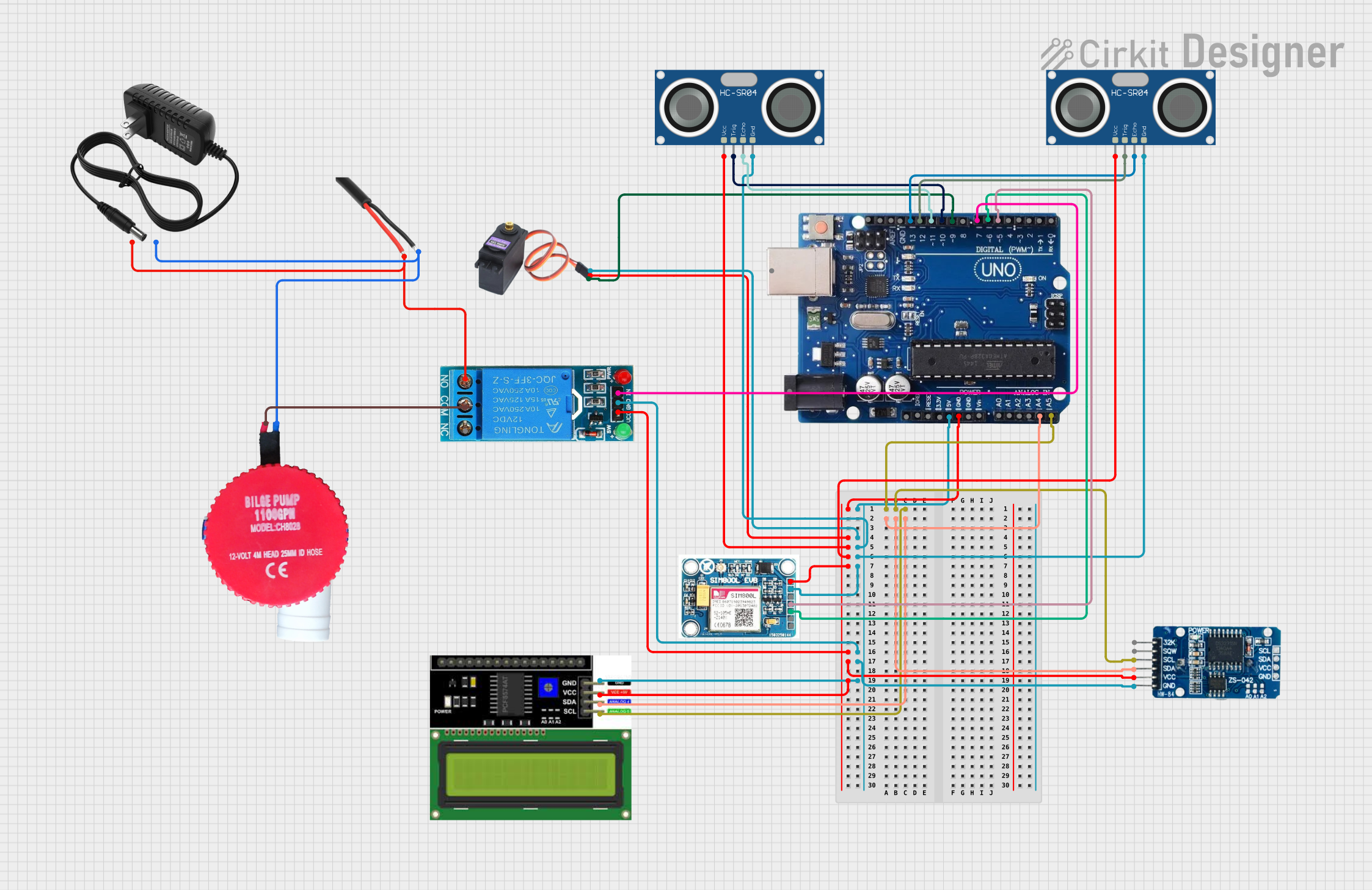
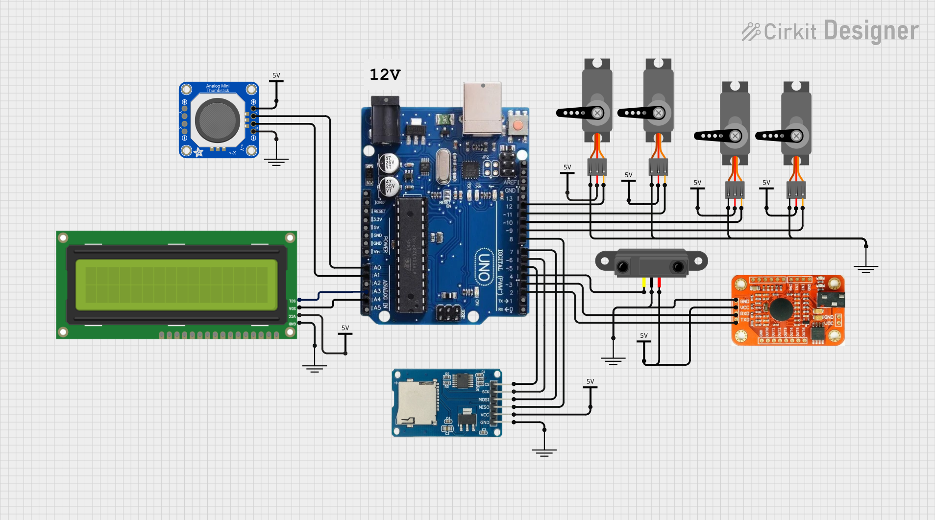
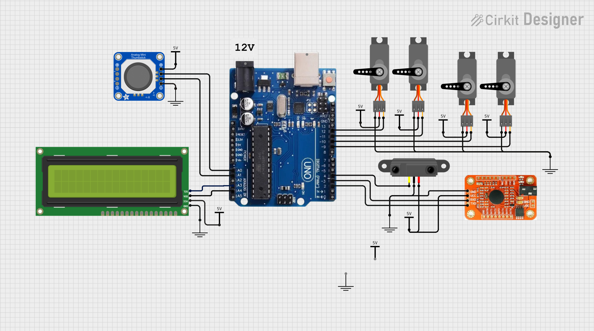
Explore Projects Built with Arduino Uno R3
Technical Specifications
Key Technical Details
| Specification | Value |
|---|---|
| Microcontroller | ATmega328P |
| Operating Voltage | 5V |
| Input Voltage | 7-12V |
| Digital I/O Pins | 14 (6 PWM output) |
| Analog Input Pins | 6 |
| DC Current per I/O Pin | 20 mA |
| Flash Memory | 32 KB (ATmega328P) |
| SRAM | 2 KB (ATmega328P) |
| EEPROM | 1 KB (ATmega328P) |
| Clock Speed | 16 MHz |
Pin Configuration and Descriptions
| Pin Number | Pin Name | Description |
|---|---|---|
| 1-14 | D0-D13 | Digital I/O pins (D0-RX, D1-TX, D3, D5, D6, D9, D10, D11 support PWM) |
| 15-20 | A0-A5 | Analog input pins |
| 21 | GND | Ground |
| 22 | 5V | 5V output |
| 23 | 3.3V | 3.3V output |
| 24 | VIN | Input voltage to the Arduino board |
| 25 | RESET | Reset pin |
| 26 | IOREF | Provides the voltage reference for the I/O pins |
| 27 | AREF | Analog reference pin for the analog inputs |
Usage Instructions
How to Use the Component in a Circuit
Powering the Arduino Uno R3:
- Connect the board to your computer using a USB cable for power and programming.
- Alternatively, use an external power supply (7-12V) connected to the power jack.
Connecting Digital I/O:
- Use digital pins (D0-D13) for digital input/output operations.
- For PWM output, use pins D3, D5, D6, D9, D10, and D11.
Connecting Analog Inputs:
- Use analog pins (A0-A5) to read analog signals (0-5V).
Programming the Arduino:
- Open the Arduino IDE on your computer.
- Select the correct board and port from the Tools menu.
- Write your code and upload it to the board.
Important Considerations and Best Practices
- Avoid Exceeding Current Limits: Ensure that the current drawn from any I/O pin does not exceed 20 mA.
- Use Proper Power Supply: Use a regulated power supply to avoid damaging the board.
- Debounce Buttons: When using buttons, implement debouncing to avoid false triggers.
- Use Pull-up/Pull-down Resistors: For stable digital input readings, use pull-up or pull-down resistors.
Example Code
Here is an example code to blink an LED connected to digital pin 13:
// Blink an LED connected to digital pin 13

void setup() {
  // Initialize digital pin 13 as an output.
  pinMode(13, OUTPUT);
}

void loop() {
  // Turn the LED on (HIGH is the voltage level)
  digitalWrite(13, HIGH);
  delay(1000); // Wait for a second

  // Turn the LED off by making the voltage LOW
  digitalWrite(13, LOW);
  delay(1000); // Wait for a second
}
Troubleshooting and FAQs
Common Issues Users Might Face
Board Not Recognized by Computer:
- Ensure the USB cable is properly connected.
- Check if the correct board and port are selected in the Arduino IDE.
Upload Error:
- Press the reset button on the board before uploading.
- Ensure no other software is using the COM port.
Incorrect Readings from Analog Pins:
- Verify the sensor connections and power supply.
- Use proper grounding and shielding to avoid noise.
Solutions and Tips for Troubleshooting
- Check Connections: Ensure all connections are secure and correct.
- Use Serial Monitor: Use the Serial Monitor in the Arduino IDE to debug and print messages.
- Update Drivers: Ensure that the latest drivers for the Arduino board are installed.
- Consult Documentation: Refer to the official Arduino documentation and forums for additional help.
By following this documentation, users can effectively utilize the Arduino Uno R3 for their projects, ensuring proper setup, usage, and troubleshooting.