How to Use C25XP v5 - Ethernet Smooth Stepper Integrated board: Examples, Pinouts, and Specs
Introduction
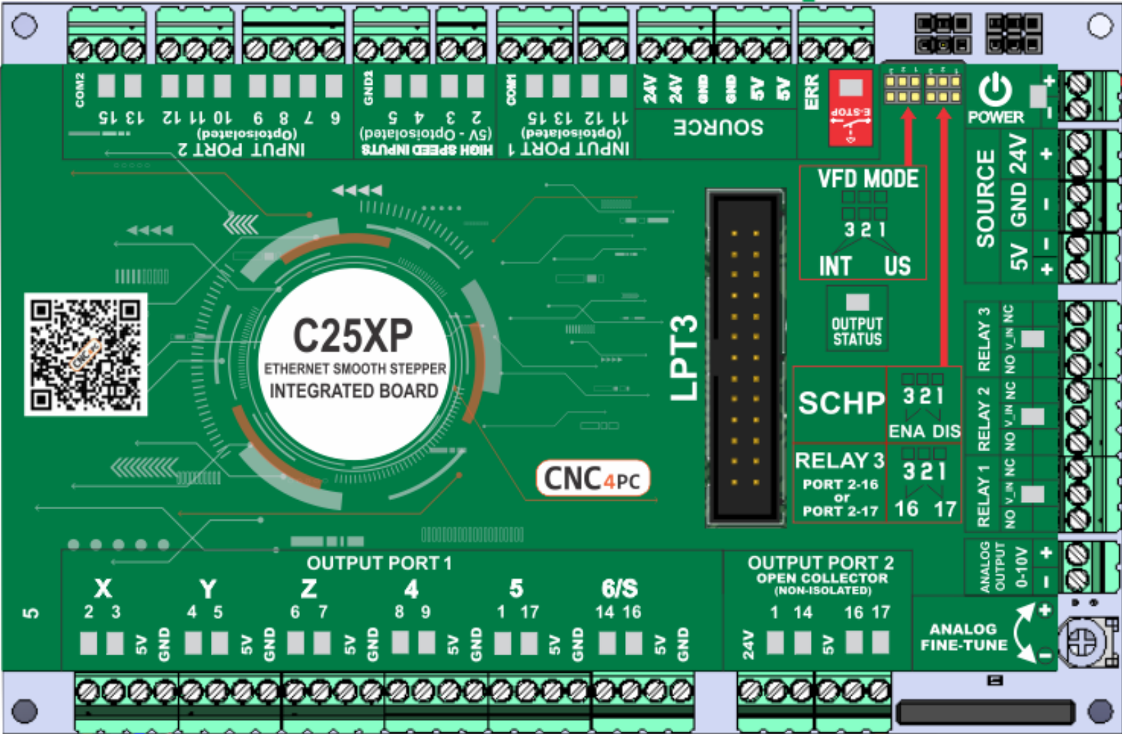
The C25XP V5 is a high-performance motion control board manufactured by CNC4PC. It is designed specifically for CNC applications, offering seamless integration with stepper motor drivers. The board features Ethernet connectivity, enabling fast and reliable communication between the control software and the hardware. With its robust design and advanced features, the C25XP V5 is ideal for precision motion control in industrial and hobbyist CNC machines.
Explore Projects Built with C25XP v5 - Ethernet Smooth Stepper Integrated board

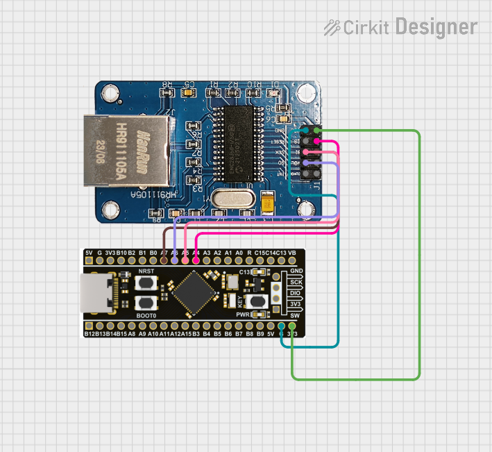
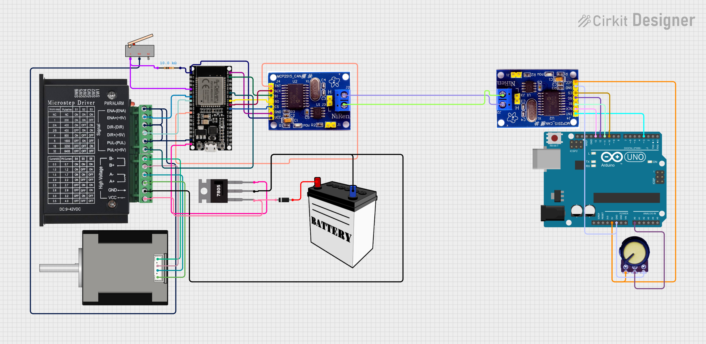
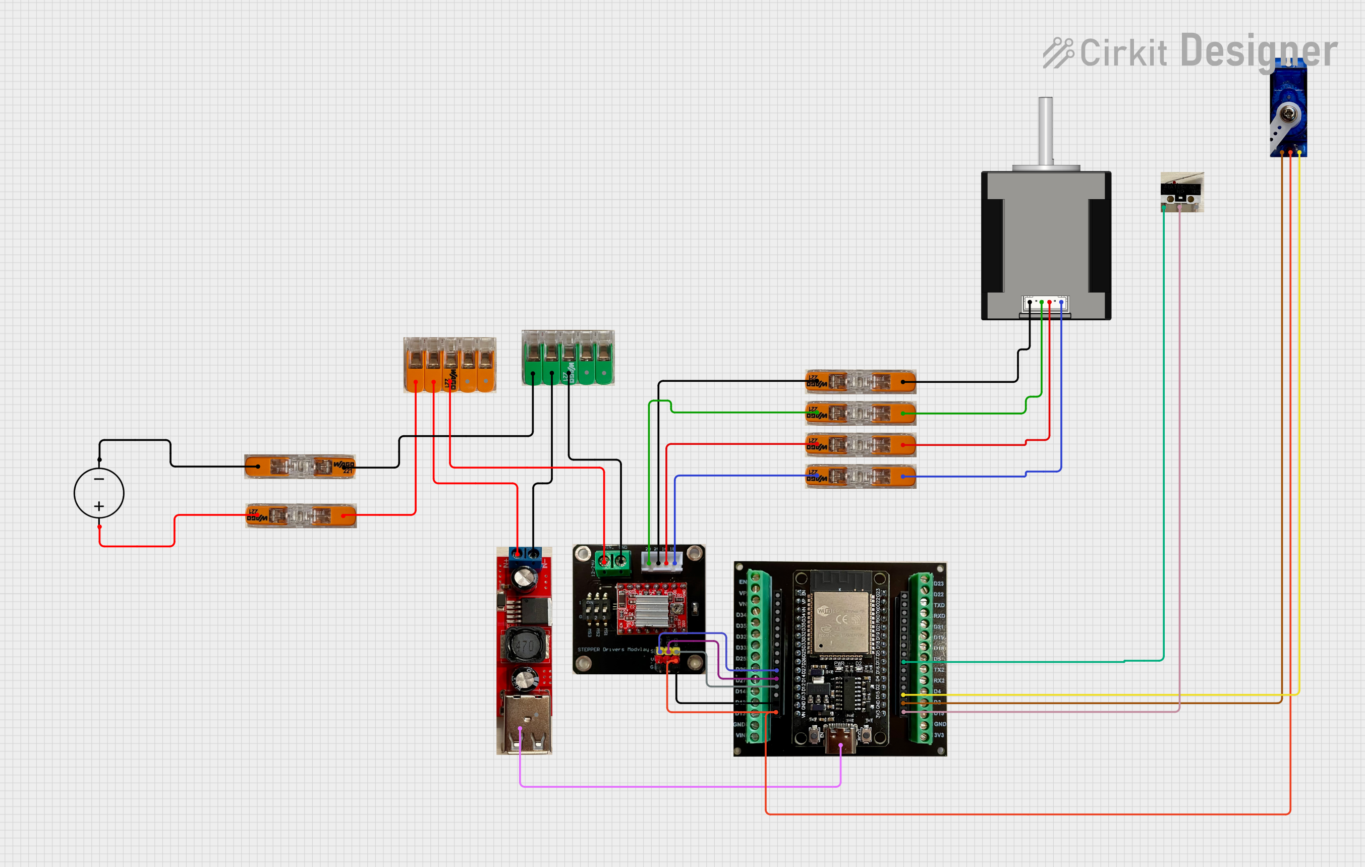
Explore Projects Built with C25XP v5 - Ethernet Smooth Stepper Integrated board
Common Applications and Use Cases
- CNC routers, mills, and lathes
- Plasma cutters and laser engravers
- 3D printers requiring precise motion control
- Automation systems requiring stepper motor control
- Educational and research projects in robotics and motion control
Technical Specifications
Key Technical Details
| Specification | Value |
|---|---|
| Manufacturer | CNC4PC |
| Part ID | C25XP V5 |
| Communication Interface | Ethernet |
| Input Voltage Range | 5V DC (logic power) |
| Stepper Motor Control | Up to 6 axes |
| Maximum Step Frequency | 4 MHz |
| Input/Output Pins | 24 opto-isolated I/O pins |
| Supported Software | Mach3, Mach4 |
| Dimensions | 5.5" x 3.5" (approx.) |
| Operating Temperature Range | 0°C to 50°C |
Pin Configuration and Descriptions
The C25XP V5 features a well-organized pinout for easy integration with stepper motor drivers and other peripherals. Below is the pin configuration:
Input/Output Pin Descriptions
| Pin Number | Pin Name | Description |
|---|---|---|
| 1-6 | Step/Dir Pins | Step and direction signals for up to 6 axes |
| 7-12 | Input Pins | Opto-isolated inputs for limit switches, |
| probes, or other sensors | ||
| 13-18 | Output Pins | Opto-isolated outputs for relays, solenoids |
| 19-24 | General I/O | Configurable as input or output |
Power and Communication Pins
| Pin Name | Description |
|---|---|
| +5V | Logic power input (5V DC) |
| GND | Ground |
| Ethernet | RJ45 connector for Ethernet communication |
Usage Instructions
How to Use the C25XP V5 in a Circuit
Powering the Board:
- Connect a regulated 5V DC power supply to the
+5VandGNDpins. Ensure the power supply can provide sufficient current for the board and connected peripherals.
- Connect a regulated 5V DC power supply to the
Connecting Stepper Drivers:
- Use the
Step/Dirpins to connect the step and direction signals to your stepper motor drivers. Each axis requires two pins: one for the step signal and one for the direction signal.
- Use the
Ethernet Communication:
- Connect the board to your PC or control system using an Ethernet cable. Configure the IP address in the control software (e.g., Mach3 or Mach4) to establish communication.
Input/Output Connections:
- Connect limit switches, probes, or other sensors to the input pins.
- Use the output pins to control relays, solenoids, or other actuators.
Software Configuration:
- Install the required plugin for Mach3 or Mach4 from the CNC4PC website.
- Configure the pin assignments and motion parameters in the software to match your hardware setup.
Important Considerations and Best Practices
- Ensure proper grounding to avoid electrical noise and interference.
- Use shielded cables for stepper motor connections to minimize EMI.
- Verify the power supply voltage and polarity before powering the board.
- Always test the system with the motors disconnected to ensure proper configuration.
Example Code for Arduino UNO Integration
While the C25XP V5 is primarily designed for use with Mach3/Mach4, it can also be interfaced with an Arduino UNO for custom applications. Below is an example of generating step and direction signals for one axis:
// Define pin numbers for step and direction signals
const int stepPin = 2;  // Step signal output
const int dirPin = 3;   // Direction signal output

void setup() {
  // Set step and direction pins as outputs
  pinMode(stepPin, OUTPUT);
  pinMode(dirPin, OUTPUT);

  // Set initial direction
  digitalWrite(dirPin, LOW); // LOW = one direction, HIGH = opposite direction
}

void loop() {
  // Generate step pulses
  digitalWrite(stepPin, HIGH); // Set step pin HIGH
  delayMicroseconds(10);       // Pulse width (10 microseconds)
  digitalWrite(stepPin, LOW);  // Set step pin LOW
  delayMicroseconds(1000);     // Delay between steps (adjust for speed)
}
Troubleshooting and FAQs
Common Issues and Solutions
No Communication with the Board:
- Ensure the Ethernet cable is securely connected.
- Verify the IP address configuration in the control software.
- Check that the board is powered on and the status LEDs are active.
Stepper Motors Not Moving:
- Verify the step and direction connections to the motor drivers.
- Check the motor driver enable signal (if applicable).
- Ensure the control software is configured with the correct pin assignments.
Inputs Not Responding:
- Confirm that the input devices (e.g., limit switches) are properly connected.
- Check the polarity and voltage levels of the input signals.
- Test the inputs using a multimeter or diagnostic tool.
Outputs Not Activating:
- Verify the output connections to the relays or actuators.
- Check the control software configuration for the output pins.
- Ensure the output devices are within the board's voltage and current limits.
FAQs
Q: Can the C25XP V5 be used with software other than Mach3/Mach4?
A: The board is optimized for Mach3 and Mach4, but it can be used with custom software or microcontrollers if the Ethernet protocol is implemented correctly.
Q: What is the maximum cable length for Ethernet communication?
A: The maximum recommended length for Ethernet cables is 100 meters (328 feet).
Q: Does the board support closed-loop stepper motors?
A: Yes, the board can interface with closed-loop stepper drivers, but the feedback loop is managed by the driver, not the board.
Q: Is the board compatible with servo motors?
A: The board can control servo motors if the servo drivers accept step and direction signals.
This concludes the documentation for the C25XP V5 - Ethernet Smooth Stepper Integrated Board. For further assistance, refer to the CNC4PC website or contact their technical support.