How to Use ESP32-S3 AMOLED1.8: Examples, Pinouts, and Specs
Introduction
The ESP32-S3 AMOLED1.8 is a compact development board manufactured by Waveshare. It integrates the powerful ESP32-S3 microcontroller with a 1.8-inch AMOLED display, making it ideal for IoT applications, wearable devices, and projects requiring a vibrant graphical interface. The board also features capacitive touch buttons, enabling intuitive user interaction.
This component is widely used in:
- IoT devices with graphical user interfaces
- Wearable electronics
- Smart home automation systems
- Portable data visualization tools
- Educational and prototyping projects
Explore Projects Built with ESP32-S3 AMOLED1.8


Explore Projects Built with ESP32-S3 AMOLED1.8
Technical Specifications
The following table outlines the key technical details of the ESP32-S3 AMOLED1.8:
| Parameter | Specification |
|---|---|
| Manufacturer | Waveshare |
| Part ID | ESP32-S3-Touch-AMOLED-1.8 |
| Microcontroller | ESP32-S3 (Xtensa® 32-bit LX7 dual-core processor) |
| Flash Memory | 16 MB |
| PSRAM | 8 MB |
| Display | 1.8-inch AMOLED, 160x128 resolution |
| Touch Input | 6 capacitive touch buttons |
| Communication Interfaces | UART, SPI, I2C, I2S, CAN, Ethernet, BLE 5.0, Wi-Fi |
| Operating Voltage | 3.3V |
| Power Supply | USB Type-C (5V input) |
| Dimensions | 50mm x 25mm |
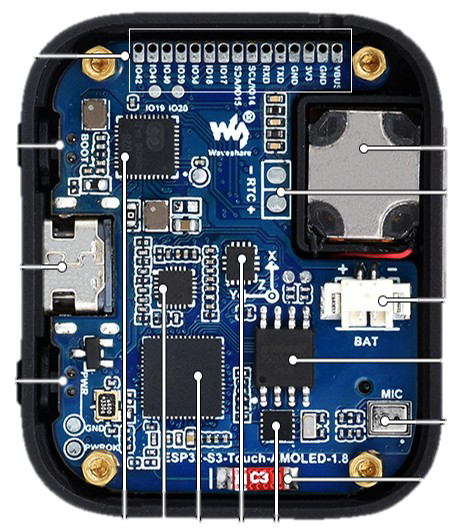
Pin Configuration and Descriptions
The ESP32-S3 AMOLED1.8 features a 24-pin header. Below is the pinout description:
| Pin | Name | Function | Description |
|---|---|---|---|
| 1 | 3V3 | Power | 3.3V power output |
| 2 | GND | Ground | Ground connection |
| 3 | IO0 | GPIO0 | General-purpose I/O |
| 4 | IO1 | GPIO1 | General-purpose I/O |
| 5 | IO2 | GPIO2 | General-purpose I/O |
| 6 | IO3 | GPIO3 | General-purpose I/O |
| 7 | IO4 | GPIO4 | General-purpose I/O |
| 8 | IO5 | GPIO5 | General-purpose I/O |
| 9 | RXD | UART RX | UART receive pin |
| 10 | TXD | UART TX | UART transmit pin |
| 11 | SCL | I2C Clock | I2C clock line |
| 12 | SDA | I2C Data | I2C data line |
| 13 | MOSI | SPI Master Out, Slave In | SPI data output |
| 14 | MISO | SPI Master In, Slave Out | SPI data input |
| 15 | SCK | SPI Clock | SPI clock line |
| 16 | CS | SPI Chip Select | SPI chip select |
| 17 | EN | Enable | Enable pin for the ESP32-S3 |
| 18 | TOUCH1 | Capacitive Touch Button 1 | Touch input 1 |
| 19 | TOUCH2 | Capacitive Touch Button 2 | Touch input 2 |
| 20 | TOUCH3 | Capacitive Touch Button 3 | Touch input 3 |
| 21 | TOUCH4 | Capacitive Touch Button 4 | Touch input 4 |
| 22 | TOUCH5 | Capacitive Touch Button 5 | Touch input 5 |
| 23 | TOUCH6 | Capacitive Touch Button 6 | Touch input 6 |
| 24 | RST | Reset | Reset pin for the ESP32-S3 |
Usage Instructions
How to Use the Component in a Circuit
- Powering the Board: Connect the ESP32-S3 AMOLED1.8 to a 5V USB power source via the USB Type-C port.
- Programming: Use the USB connection to upload code to the ESP32-S3 using the Arduino IDE, PlatformIO, or ESP-IDF.
- Connecting Peripherals: Use the GPIO pins to interface with external sensors, actuators, or other devices. Ensure the voltage levels are compatible (3.3V logic).
- Using the Display: The 1.8-inch AMOLED display can be controlled via SPI. Libraries such as
Adafruit_GFXandAdafruit_ST7735are compatible. - Touch Buttons: The capacitive touch buttons can be read as digital inputs. Use the
touchRead()function in the Arduino IDE to detect touch events.
Important Considerations and Best Practices
- Power Supply: Ensure a stable 5V power source to avoid display flickering or microcontroller instability.
- Pin Protection: Avoid applying voltages higher than 3.3V to the GPIO pins to prevent damage.
- Display Handling: Avoid applying excessive pressure to the AMOLED screen to prevent damage.
- Firmware Updates: Keep the ESP32-S3 firmware updated for optimal performance and compatibility.
Example Code for Arduino UNO
Below is an example of how to display text on the AMOLED screen and read touch input:
#include <Adafruit_GFX.h>
#include <Adafruit_ST7735.h>

// Define SPI pins for the display
#define TFT_CS   15  // Chip select pin
#define TFT_RST  17  // Reset pin
#define TFT_DC   16  // Data/command pin

// Initialize the display object
Adafruit_ST7735 tft = Adafruit_ST7735(TFT_CS, TFT_DC, TFT_RST);

void setup() {
  // Initialize serial communication
  Serial.begin(115200);

  // Initialize the display
  tft.initR(INITR_BLACKTAB);  // Initialize with a specific tab configuration
  tft.fillScreen(ST77XX_BLACK);  // Clear the screen
  tft.setTextColor(ST77XX_WHITE);  // Set text color
  tft.setTextSize(2);  // Set text size

  // Display a message
  tft.setCursor(10, 10);  // Set cursor position
  tft.println("Hello, ESP32!");

  // Initialize touch pins
  pinMode(18, INPUT);  // TOUCH1
  pinMode(19, INPUT);  // TOUCH2
}

void loop() {
  // Check if TOUCH1 is pressed
  if (digitalRead(18) == LOW) {
    Serial.println("Touch 1 Pressed!");
    tft.fillScreen(ST77XX_RED);  // Change screen color
  }

  // Check if TOUCH2 is pressed
  if (digitalRead(19) == LOW) {
    Serial.println("Touch 2 Pressed!");
    tft.fillScreen(ST77XX_BLUE);  // Change screen color
  }

  delay(100);  // Small delay for debounce
}
Troubleshooting and FAQs
Common Issues and Solutions
Display Not Working:
- Ensure the SPI connections are correct and secure.
- Verify that the display initialization code matches the hardware configuration.
- Check the power supply for sufficient voltage and current.
Touch Buttons Not Responding:
- Ensure the touch pins are properly configured as inputs.
- Verify that the touchRead() function is used correctly in the code.
- Check for electrical noise or interference affecting the touch sensors.
Microcontroller Not Detected by PC:
- Ensure the USB cable is functional and supports data transfer.
- Install the correct USB drivers for the ESP32-S3.
- Press the reset button or hold the boot button while connecting to the PC.
FAQs
Q: Can I use the ESP32-S3 AMOLED1.8 with a 5V logic device?
A: No, the GPIO pins operate at 3.3V logic. Use a level shifter if interfacing with 5V devices.
Q: What is the maximum current draw of the board?
A: The maximum current draw is approximately 500mA, depending on the peripherals and display usage.
Q: Is the display backlight adjustable?
A: Yes, the display brightness can be controlled via PWM on the backlight pin (if exposed).
Q: Can I use the board with MicroPython?
A: Yes, the ESP32-S3 is compatible with MicroPython. You can flash the MicroPython firmware and use libraries to control the display and touch inputs.