How to Use Modul rung: Examples, Pinouts, and Specs
Introduction
A Modular Rung is a fundamental component used in ladder logic diagrams, commonly employed in Programmable Logic Controllers (PLCs). It represents a single control function or operation within a control circuit. Modular rungs are designed to simplify the implementation of logical operations, such as AND, OR, and NOT, in industrial automation systems.
Explore Projects Built with Modul rung


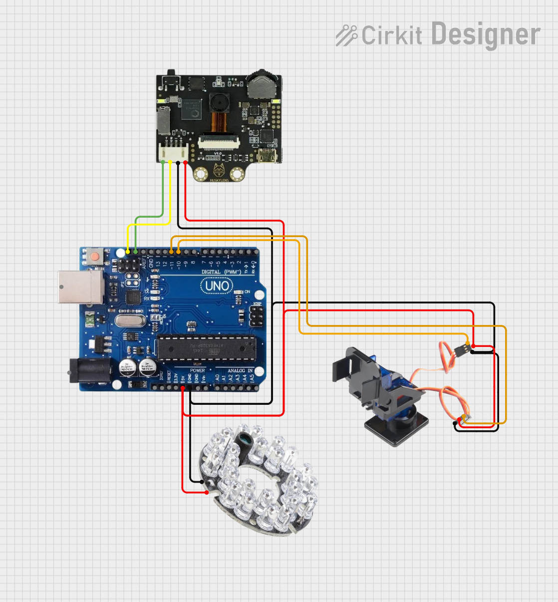
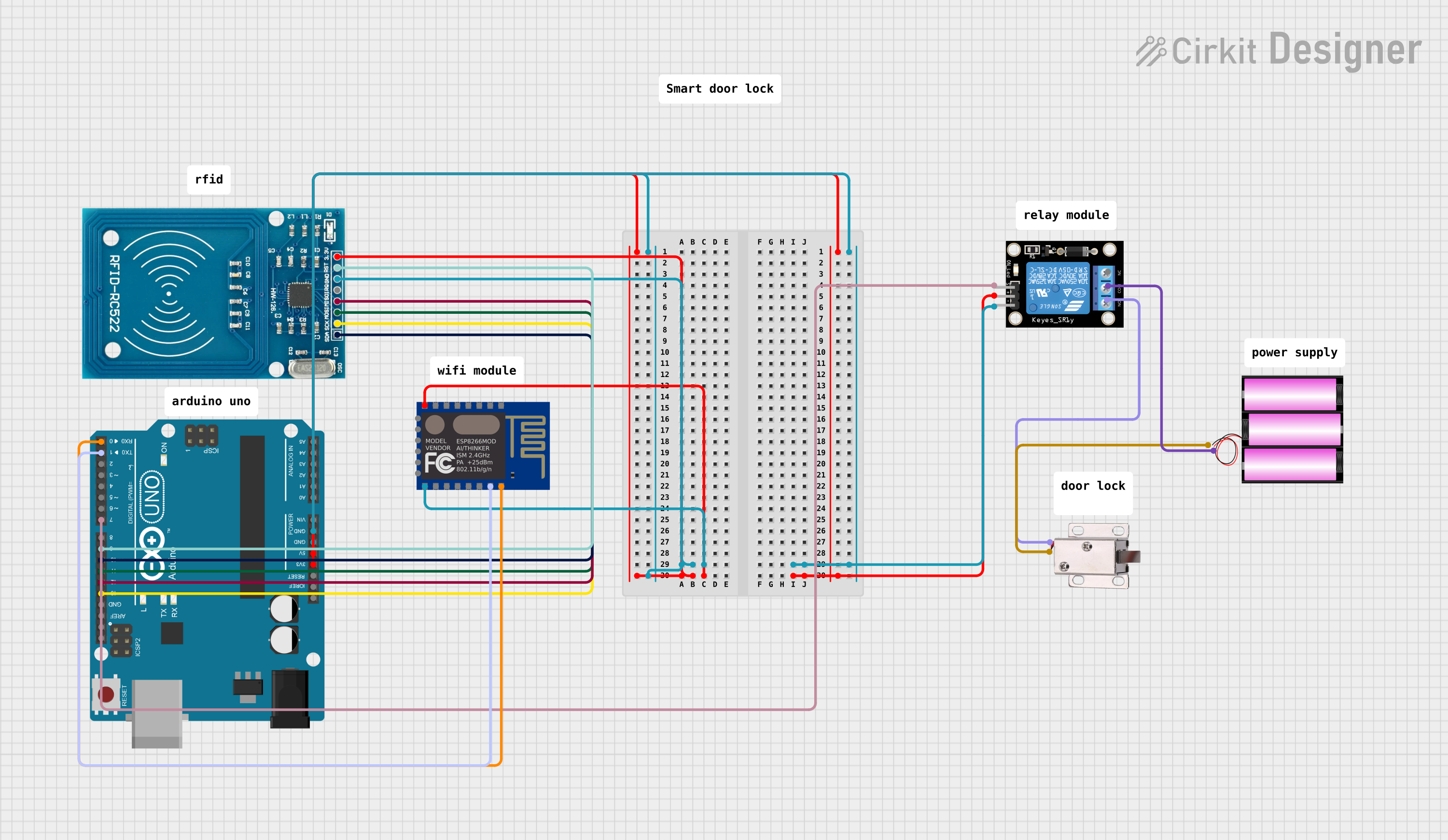
Explore Projects Built with Modul rung
Common Applications and Use Cases
- Industrial Automation: Used in PLCs to control machinery and processes.
- Process Control: Implements logical operations for sensors, actuators, and relays.
- Safety Systems: Ensures proper sequencing and interlocking in safety-critical systems.
- Building Automation: Controls HVAC, lighting, and other building systems.
Technical Specifications
Below are the key technical details for the Modular Rung manufactured by Motor (Part ID: Motor):
General Specifications
| Parameter | Value |
|---|---|
| Manufacturer | Motor |
| Part ID | Motor |
| Functionality | Logical operation in PLCs |
| Operating Voltage | 24V DC (typical for PLCs) |
| Current Rating | 10 mA (logic-level operation) |
| Operating Temperature | -20°C to 70°C |
| Storage Temperature | -40°C to 85°C |
| Dimensions | Modular, varies by PLC model |
Pin Configuration and Descriptions
The modular rung is typically implemented as part of a PLC's internal architecture. However, for external interfacing, the following pin configuration is common:
| Pin Number | Pin Name | Description |
|---|---|---|
| 1 | Input A | First input for logical operation (e.g., sensor) |
| 2 | Input B | Second input for logical operation |
| 3 | Output | Logical result of the operation |
| 4 | Common (GND) | Ground connection for the circuit |
| 5 | VCC | Power supply (24V DC typical) |
Usage Instructions
How to Use the Modular Rung in a Circuit
- Connect Inputs: Attach the input signals (e.g., from sensors or switches) to the
Input AandInput Bpins. - Power the Circuit: Provide a 24V DC power supply to the
VCCpin and connect theCommon (GND)pin to ground. - Monitor Output: The logical result of the operation will be available at the
Outputpin. This can be connected to an actuator, relay, or another PLC input.
Important Considerations and Best Practices
- Voltage Levels: Ensure the input and output signals are within the specified voltage range to avoid damage.
- Debouncing: Use debouncing techniques for mechanical switches to prevent false triggering.
- Isolation: For high-voltage or noisy environments, consider using optoisolators or relays to protect the PLC.
- Programming: Configure the PLC ladder logic to define the desired operation (e.g., AND, OR, NOT).
Example: Connecting to an Arduino UNO
While modular rungs are primarily used in PLCs, you can simulate their functionality using an Arduino UNO. Below is an example code snippet to implement an AND operation:
// Define input pins for the modular rung simulation
const int inputA = 2;  // Input A connected to digital pin 2
const int inputB = 3;  // Input B connected to digital pin 3
const int outputPin = 13; // Output connected to the onboard LED (pin 13)

void setup() {
  pinMode(inputA, INPUT);  // Set Input A as input
  pinMode(inputB, INPUT);  // Set Input B as input
  pinMode(outputPin, OUTPUT); // Set Output as output
}

void loop() {
  // Read the state of Input A and Input B
  int stateA = digitalRead(inputA);
  int stateB = digitalRead(inputB);

  // Perform AND operation and set the output
  if (stateA == HIGH && stateB == HIGH) {
    digitalWrite(outputPin, HIGH); // Turn on the output if both inputs are HIGH
  } else {
    digitalWrite(outputPin, LOW);  // Turn off the output otherwise
  }
}
Troubleshooting and FAQs
Common Issues and Solutions
No Output Signal:
- Cause: Incorrect wiring or loose connections.
- Solution: Verify all connections and ensure proper wiring as per the pin configuration.
Erratic Behavior:
- Cause: Noise or interference in the input signals.
- Solution: Use shielded cables and proper grounding. Add debounce logic for mechanical switches.
Overheating:
- Cause: Exceeding the current or voltage ratings.
- Solution: Ensure the input and output signals are within the specified range.
PLC Not Responding:
- Cause: Incorrect ladder logic programming.
- Solution: Double-check the ladder logic diagram and ensure the modular rung is correctly configured.
FAQs
Q1: Can the modular rung handle analog signals?
A1: No, modular rungs are designed for digital signals. Use an analog-to-digital converter (ADC) for analog inputs.
Q2: What happens if only one input is connected?
A2: The output will depend on the ladder logic configuration. For an AND operation, the output will remain LOW.
Q3: Can I use a modular rung with a 12V power supply?
A3: Modular rungs are typically designed for 24V DC. Using a lower voltage may result in unreliable operation.
Q4: How do I expand the functionality of a modular rung?
A4: Combine multiple rungs in the ladder logic diagram to implement complex operations.