
How to Use ICL7660: Examples, Pinouts, and Specs
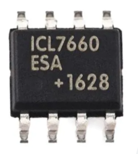
 Design with ICL7660 in Cirkit Designer
Introduction
The ICL7660 is a versatile voltage converter integrated circuit (IC) designed to generate a negative voltage from a positive voltage supply. It operates using a charge-pump principle, making it an efficient and compact solution for applications requiring a dual power supply. This IC is widely used in analog circuits, operational amplifiers, and other systems where a negative voltage rail is essential but only a single positive voltage source is available.
Explore Projects Built with ICL7660
 Open Project in Cirkit Designer
 Open Project in Cirkit Designer
 Open Project in Cirkit Designer
 Open Project in Cirkit Designer
Explore Projects Built with ICL7660
Open Project in Cirkit DesignerOpen Project in Cirkit DesignerOpen Project in Cirkit DesignerOpen Project in Cirkit DesignerCommon Applications
- Dual power supply generation for operational amplifiers
- Analog signal processing circuits
- Battery-powered devices
- Portable instrumentation
- Voltage inverters for low-power applications
Technical Specifications
The ICL7660 is designed for low-power applications and offers reliable performance with minimal external components. Below are its key technical specifications:
| Parameter | Value |
|---|---|
| Input Voltage Range | 1.5V to 10V |
| Output Voltage Range | -1.5V to -10V (approximately -Vin) |
| Maximum Output Current | 20mA (typical) |
| Quiescent Current | 200µA (typical) |
| Efficiency | Up to 98% |
| Operating Temperature Range | 0°C to +70°C |
| Package Types | DIP-8, SOIC-8 |
Pin Configuration and Descriptions
The ICL7660 is typically available in an 8-pin DIP or SOIC package. Below is the pinout and description:
| Pin Number | Pin Name | Description |
|---|---|---|
| 1 | V+ | Positive power supply input (1.5V to 10V). |
| 2 | CAP+ | Positive terminal for the external charge-pump capacitor. |
| 3 | GND | Ground (0V reference). |
| 4 | CAP- | Negative terminal for the external charge-pump capacitor. |
| 5 | VOUT | Negative voltage output (approximately -Vin). |
| 6 | LV | Low-voltage pin (connect to GND for input voltage < 3.5V; leave open otherwise). |
| 7 | OSC | Oscillator control pin (leave open for internal oscillator; connect external |
| components for custom frequency). | ||
| 8 | V+ | Positive power supply input (same as Pin 1). |
Usage Instructions
How to Use the ICL7660 in a Circuit
- Power Supply: Connect the positive voltage source (1.5V to 10V) to the
V+pin and ground to theGNDpin. - Charge-Pump Capacitors:
- Connect a capacitor (typically 10µF) between the
CAP+andCAP-pins. - Connect another capacitor (typically 10µF) between the
VOUTpin andGND.
- Connect a capacitor (typically 10µF) between the
- Low Voltage Operation: If the input voltage is below 3.5V, connect the
LVpin toGND. For higher input voltages, leave theLVpin unconnected. - Oscillator: For most applications, leave the
OSCpin unconnected to use the internal oscillator. If a custom frequency is required, connect external components to this pin as per the datasheet.
Example Circuit
Below is a basic circuit diagram for using the ICL7660 to generate a -5V output from a +5V input:
+5V ----[10µF]---- CAP+ (Pin 2) ---- CAP- (Pin 4) ----[10µF]---- GND
  |                          |                          |
  |                          |                          |
 V+ (Pin 1)              VOUT (Pin 5)               GND (Pin 3)
Arduino UNO Example
The ICL7660 can be used in Arduino projects to provide a negative voltage rail for operational amplifiers or other analog components. Below is an example code snippet to demonstrate its use:
// Example: Using ICL7660 to generate -5V for an op-amp in an Arduino project

void setup() {
  // Initialize serial communication for debugging
  Serial.begin(9600);

  // Print a message to indicate the circuit is powered
  Serial.println("ICL7660 is generating -5V from +5V input.");

  // Note: The ICL7660 operates independently of Arduino control.
  // Ensure the circuit is connected as per the datasheet.
}

void loop() {
  // No control is required for the ICL7660; it operates autonomously.
  // You can use the -5V output for other components in your circuit.
}
Best Practices
- Use low-ESR capacitors (e.g., ceramic or tantalum) for optimal performance.
- Ensure the input voltage does not exceed the maximum rating of 10V.
- Keep the charge-pump capacitors close to the IC to minimize noise and improve efficiency.
- For higher output currents, consider using larger capacitors (e.g., 22µF or 47µF).
Troubleshooting and FAQs
Common Issues and Solutions
Output Voltage is Incorrect or Unstable:
- Verify that the charge-pump capacitors are correctly connected and have the recommended capacitance (10µF or higher).
- Check for loose connections or poor solder joints.
- Ensure the input voltage is within the specified range (1.5V to 10V).
IC Overheating:
- Ensure the output current does not exceed the maximum rating of 20mA.
- Check for short circuits on the output.
No Output Voltage:
- Confirm that the
LVpin is connected toGNDif the input voltage is below 3.5V. - Verify that the
OSCpin is properly configured (leave open for internal oscillator).
- Confirm that the
FAQs
Q: Can the ICL7660 provide a regulated output voltage?
A: No, the ICL7660 is not a voltage regulator. The output voltage is approximately equal to the negative of the input voltage (-Vin). For regulated output, additional circuitry is required.
Q: What is the maximum output current of the ICL7660?
A: The typical maximum output current is 20mA. Exceeding this limit may cause instability or damage to the IC.
Q: Can I use the ICL7660 with an input voltage higher than 10V?
A: No, the maximum input voltage is 10V. Exceeding this value may permanently damage the IC.
Q: What type of capacitors should I use with the ICL7660?
A: Low-ESR capacitors, such as ceramic or tantalum capacitors, are recommended for optimal performance.
By following the guidelines and best practices outlined in this documentation, you can effectively use the ICL7660 in your electronic projects.