Cirkit Designer Logo
Cirkit Designer
Your all-in-one circuit design IDE
Home / 
Component Documentation

How to Use Arduino Opta RS485: Examples, Pinouts, and Specs

Image of Arduino Opta RS485
Cirkit Designer LogoDesign with Arduino Opta RS485 in Cirkit Designer

Introduction

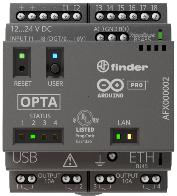
The Arduino Opta RS485 (Manufacturer Part ID: AFX00002) is a compact and robust microcontroller designed for industrial automation and IoT applications. Developed in collaboration with Finder, this Programmable Logic Controller (PLC) combines the simplicity of Arduino programming with the reliability required for industrial environments. It features RS485 communication, making it ideal for Modbus RTU and other industrial communication protocols.

Explore Projects Built with Arduino Opta RS485

Use Cirkit Designer to design, explore, and prototype these projects online. Some projects support real-time simulation. Click "Open Project" to start designing instantly!
STM32 and Arduino UNO Based Dual RS485 Communication Interface
Image of STM to Arduino RS485: A project utilizing Arduino Opta RS485 in a practical application
This circuit consists of two microcontrollers, an STM32F103C8T6 and an Arduino UNO, each interfaced with separate RS485 transceiver modules for serial communication. The STM32F103C8T6 controls the RE (Receiver Enable) and DE (Driver Enable) pins of one RS485 module to manage its operation, and communicates via the A9 and A10 pins for DI (Data Input) and RO (Receiver Output), respectively. The Arduino UNO is similarly connected to another RS485 module, with digital pins D2 and D3 interfacing with DI and RO, and D8 controlling both RE and DE. The RS485 modules are connected to each other through their A and B differential communication lines, enabling serial data exchange between the two microcontrollers over a robust and long-distance capable RS485 network.
Cirkit Designer LogoOpen Project in Cirkit Designer
ESP32-Based Industrial Control System with RS485 Communication and I2C Interface
Image of DRIVER TESTER : A project utilizing Arduino Opta RS485 in a practical application
This circuit integrates a microcontroller with a display, digital potentiometer, IO expander, and opto-isolator board for signal interfacing and isolation. It includes a UART to RS485 converter for serial communication and a power converter to step down voltage for the system. The circuit is designed for control and communication in an isolated and protected environment.
Cirkit Designer LogoOpen Project in Cirkit Designer
Arduino UNO-Based RS485 Communication System with Potentiometer-Controlled LEDs
Image of CircuitoSimulacion: A project utilizing Arduino Opta RS485 in a practical application
This circuit uses an Arduino UNO to read analog signals from three rotary potentiometers and control three LEDs through current-limiting resistors. Additionally, it interfaces with a UART TTL to RS485 converter for serial communication, which is connected to an RS485 to USB converter for data transmission to a computer. The circuit is powered by a 5V PSU connected to a 220V power source.
Cirkit Designer LogoOpen Project in Cirkit Designer
Arduino UNO Based RS-485 Communication System with Pushbutton Activation and LED Indicator
Image of tp: A project utilizing Arduino Opta RS485 in a practical application
This circuit consists of two Arduino UNO microcontrollers interfaced with RS-485 modules to enable serial communication over a differential bus, allowing for robust long-distance data transmission. One Arduino is configured as a master, sending a message when a pushbutton is pressed, while the other Arduino is set up as a slave, responding by lighting up an LED when the correct message is received. The system is powered by two separate 9V batteries, and a resistor is used to limit the current through the LED.
Cirkit Designer LogoOpen Project in Cirkit Designer

Explore Projects Built with Arduino Opta RS485

Use Cirkit Designer to design, explore, and prototype these projects online. Some projects support real-time simulation. Click "Open Project" to start designing instantly!
Image of STM to Arduino RS485: A project utilizing Arduino Opta RS485 in a practical application
STM32 and Arduino UNO Based Dual RS485 Communication Interface
This circuit consists of two microcontrollers, an STM32F103C8T6 and an Arduino UNO, each interfaced with separate RS485 transceiver modules for serial communication. The STM32F103C8T6 controls the RE (Receiver Enable) and DE (Driver Enable) pins of one RS485 module to manage its operation, and communicates via the A9 and A10 pins for DI (Data Input) and RO (Receiver Output), respectively. The Arduino UNO is similarly connected to another RS485 module, with digital pins D2 and D3 interfacing with DI and RO, and D8 controlling both RE and DE. The RS485 modules are connected to each other through their A and B differential communication lines, enabling serial data exchange between the two microcontrollers over a robust and long-distance capable RS485 network.
Cirkit Designer LogoOpen Project in Cirkit Designer
Image of DRIVER TESTER : A project utilizing Arduino Opta RS485 in a practical application
ESP32-Based Industrial Control System with RS485 Communication and I2C Interface
This circuit integrates a microcontroller with a display, digital potentiometer, IO expander, and opto-isolator board for signal interfacing and isolation. It includes a UART to RS485 converter for serial communication and a power converter to step down voltage for the system. The circuit is designed for control and communication in an isolated and protected environment.
Cirkit Designer LogoOpen Project in Cirkit Designer
Image of CircuitoSimulacion: A project utilizing Arduino Opta RS485 in a practical application
Arduino UNO-Based RS485 Communication System with Potentiometer-Controlled LEDs
This circuit uses an Arduino UNO to read analog signals from three rotary potentiometers and control three LEDs through current-limiting resistors. Additionally, it interfaces with a UART TTL to RS485 converter for serial communication, which is connected to an RS485 to USB converter for data transmission to a computer. The circuit is powered by a 5V PSU connected to a 220V power source.
Cirkit Designer LogoOpen Project in Cirkit Designer
Image of tp: A project utilizing Arduino Opta RS485 in a practical application
Arduino UNO Based RS-485 Communication System with Pushbutton Activation and LED Indicator
This circuit consists of two Arduino UNO microcontrollers interfaced with RS-485 modules to enable serial communication over a differential bus, allowing for robust long-distance data transmission. One Arduino is configured as a master, sending a message when a pushbutton is pressed, while the other Arduino is set up as a slave, responding by lighting up an LED when the correct message is received. The system is powered by two separate 9V batteries, and a resistor is used to limit the current through the LED.
Cirkit Designer LogoOpen Project in Cirkit Designer

Common Applications and Use Cases

  • Industrial automation and control systems
  • Building management systems (BMS)
  • IoT edge devices for data acquisition
  • Modbus RTU communication with sensors and actuators
  • Smart energy management systems

Technical Specifications

The Arduino Opta RS485 is equipped with powerful hardware and versatile communication interfaces. Below are its key specifications:

General Specifications

Parameter Value
Manufacturer Finder
Part Number AFX00002
Microcontroller STM32H747XI dual-core Cortex-M7/M4
Operating Voltage 24V DC
Communication Interface RS485, Ethernet, Wi-Fi, BLE
Digital Inputs 8 (24V logic)
Digital Outputs 4 relay outputs (10A @ 250V AC)
Analog Inputs 2 (0-10V)
Operating Temperature Range -40°C to +85°C
Dimensions 72mm x 90mm x 60mm

Pin Configuration and Descriptions

The Arduino Opta RS485 features a terminal block for industrial connections. Below is the pin configuration:

Power and Communication Pins

Pin Name Description
V+ 24V DC positive power input
V- 24V DC ground
A (RS485) RS485 differential signal (non-inverting)
B (RS485) RS485 differential signal (inverting)
GND Ground for RS485 communication

Digital Input Pins

Pin Name Description
DI1 - DI8 Digital inputs (24V logic)

Digital Output Pins

Pin Name Description
DO1 - DO4 Relay outputs (10A @ 250V AC)

Analog Input Pins

Pin Name Description
AI1, AI2 Analog inputs (0-10V)

Usage Instructions

How to Use the Arduino Opta RS485 in a Circuit

  1. Power Supply: Connect a 24V DC power supply to the V+ and V- terminals.
  2. RS485 Communication: Connect the RS485 A and B terminals to the corresponding A and B lines of your RS485 network. Ensure proper termination resistors are used if required.
  3. Digital Inputs: Connect 24V logic signals to the DI1-DI8 terminals for digital input sensing.
  4. Digital Outputs: Use the DO1-DO4 relay outputs to control external devices such as motors, lights, or solenoids.
  5. Analog Inputs: Connect 0-10V analog signals to AI1 and AI2 for sensor data acquisition.

Important Considerations and Best Practices

  • Ensure the power supply voltage is within the specified range (24V DC).
  • Use proper shielding and grounding for RS485 communication to minimize noise.
  • Avoid exceeding the maximum current and voltage ratings of the relay outputs.
  • Use pull-up or pull-down resistors for digital inputs if required by your application.
  • Always follow safety guidelines when working with high-voltage devices connected to the relay outputs.

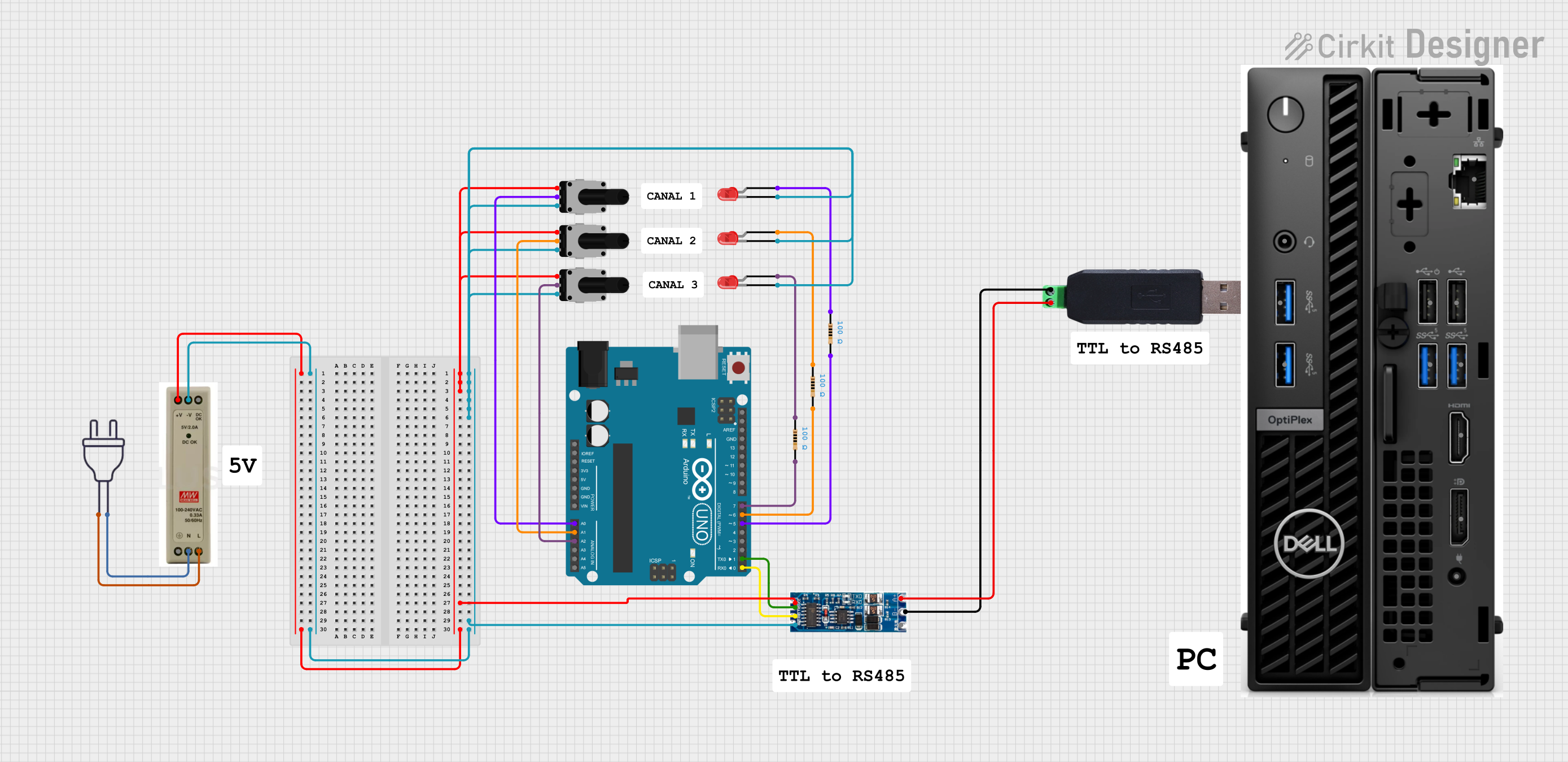
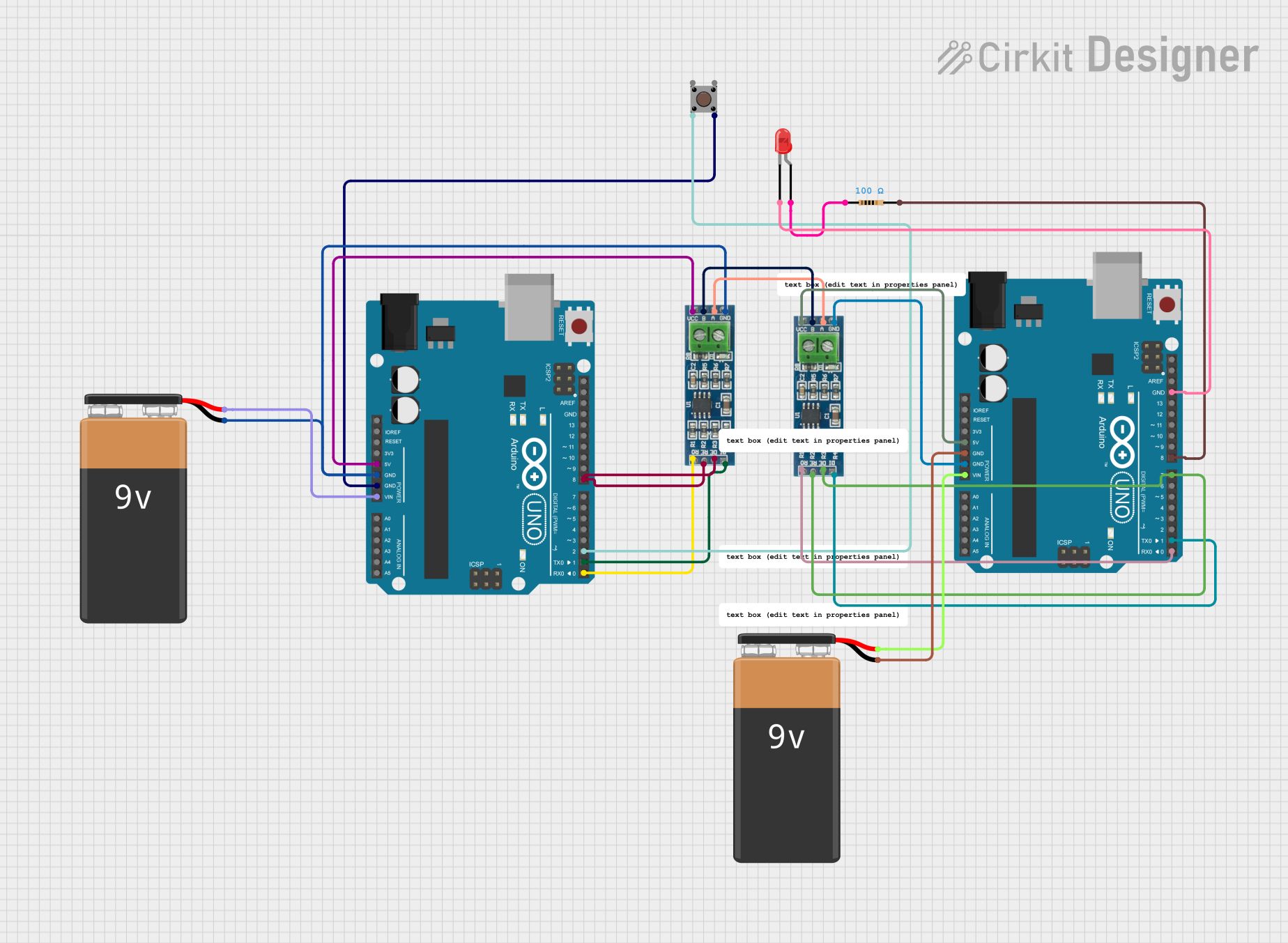
Example Code for Arduino UNO Integration

The Arduino Opta RS485 can communicate with an Arduino UNO via Modbus RTU over RS485. Below is an example code snippet:

#include <ModbusMaster.h>

// Instantiate ModbusMaster object
ModbusMaster node;

void setup() {
  // Initialize serial communication for RS485
  Serial.begin(9600);
  
  // Start Modbus communication
  node.begin(1, Serial); // Slave ID = 1
}

void loop() {
  uint8_t result;
  uint16_t data;

  // Read holding register 0x0001 from the Opta RS485
  result = node.readHoldingRegisters(0x0001, 1);

  if (result == node.ku8MBSuccess) {
    data = node.getResponseBuffer(0);
    Serial.print("Register Value: ");
    Serial.println(data);
  } else {
    Serial.println("Failed to read register");
  }

  delay(1000); // Wait 1 second before next read
}

Notes:

  • Use an RS485 transceiver module (e.g., MAX485) to connect the Arduino UNO to the Opta RS485.
  • Ensure the baud rate and Modbus settings match between the devices.

Troubleshooting and FAQs

Common Issues and Solutions

  1. RS485 Communication Not Working

    • Verify the A and B lines are correctly connected.
    • Check for proper termination resistors at both ends of the RS485 network.
    • Ensure the baud rate and Modbus settings are consistent across devices.
  2. Digital Inputs Not Responding

    • Confirm the input voltage is within the 24V logic range.
    • Check for loose or incorrect wiring.
  3. Relay Outputs Not Activating

    • Ensure the load connected to the relay output does not exceed the rated current and voltage.
    • Verify the relay control logic in your code.
  4. Analog Inputs Reading Incorrect Values

    • Check the input voltage range (0-10V) and ensure the sensor output matches this range.
    • Verify the wiring and connections to the analog input terminals.

FAQs

Q: Can the Opta RS485 be programmed using the Arduino IDE?
A: Yes, the Opta RS485 is fully compatible with the Arduino IDE, allowing for easy programming and integration.

Q: Does the Opta RS485 support wireless communication?
A: Yes, in addition to RS485, the Opta RS485 supports Ethernet, Wi-Fi, and BLE for versatile communication options.

Q: What is the maximum cable length for RS485 communication?
A: RS485 supports cable lengths up to 1200 meters, but this may vary depending on baud rate and cable quality.

Q: Can I use the Opta RS485 in outdoor environments?
A: The Opta RS485 is designed for industrial environments and can operate in temperatures ranging from -40°C to +85°C. However, ensure it is housed in a suitable enclosure for outdoor use.

This concludes the documentation for the Arduino Opta RS485. For further assistance, refer to the official Arduino and Finder resources.