Cirkit Designer Logo
Cirkit Designer
Your all-in-one circuit design IDE
Home / 
Component Documentation

How to Use DE10-Lite Development and Education Board: Examples, Pinouts, and Specs

Image of DE10-Lite Development and Education Board
Cirkit Designer LogoDesign with DE10-Lite Development and Education Board in Cirkit Designer

Introduction

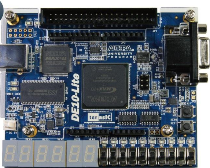
The DE10-Lite Development and Education Board is a versatile FPGA development platform designed for educational purposes and prototyping. It features an Intel MAX 10 FPGA, offering a balance of performance and flexibility for a wide range of applications. The board includes various I/O interfaces, onboard peripherals, and support for multiple programming environments, making it an excellent choice for students, hobbyists, and professionals.

Explore Projects Built with DE10-Lite Development and Education Board

Use Cirkit Designer to design, explore, and prototype these projects online. Some projects support real-time simulation. Click "Open Project" to start designing instantly!
I2C-Controlled OLED Display with External EEPROM and Interactive Pushbuttons
Image of godmode: A project utilizing DE10-Lite Development and Education Board in a practical application
This is a microcontroller-based interactive device featuring a Wemos D1 Mini, an OLED display, external EEPROM, and an I/O expander. It includes user input buttons and status LEDs, with potential MIDI interface capabilities.
Cirkit Designer LogoOpen Project in Cirkit Designer
ESP32-Based Smart Agriculture System with LoRa Communication
Image of Soil Monitoring Device: A project utilizing DE10-Lite Development and Education Board in a practical application
This circuit features an ESP32 Devkit V1 microcontroller as the central processing unit, interfacing with various sensors including a PH Meter, an NPK Soil Sensor, and a Soil Moisture Sensor for environmental data collection. It also includes an EBYTE LoRa E220 module for wireless communication. Power management is handled by a Step Up Boost Power Converter, which is connected to a 12V Battery, stepping up the voltage to power the ESP32 and sensors, with common ground connections throughout the circuit.
Cirkit Designer LogoOpen Project in Cirkit Designer
ESP32-Based Multi-Sensor Interface with GSM and Display
Image of NAAZ: A project utilizing DE10-Lite Development and Education Board in a practical application
This circuit features an ESP32 Devkit V1 microcontroller as its central processing unit, interfacing with a variety of sensors and modules for monitoring and communication purposes. It includes an LCD I2C display for user interface, a SIM800L module for GSM communication, and sensors like the Adafruit L3GD20H gyro, Adafruit ADXL377 accelerometer, DS18B20 temperature sensor, and a pulse sensor for environmental and physiological data collection. The circuit also controls a red and a green LED, each with a current-limiting resistor, and a buzzer for audio feedback, all of which are likely used for status indication or alerts.
Cirkit Designer LogoOpen Project in Cirkit Designer
ESP32-Based Display Interface with Battery Management
Image of teacher project: A project utilizing DE10-Lite Development and Education Board in a practical application
This circuit is designed to manage power from batteries and display information using an LCD and an LED dot display. It features power regulation through step-up boost converters and charging modules for the batteries, with control and data interfaces provided by two ESP32 microcontrollers for the displays.
Cirkit Designer LogoOpen Project in Cirkit Designer

Explore Projects Built with DE10-Lite Development and Education Board

Use Cirkit Designer to design, explore, and prototype these projects online. Some projects support real-time simulation. Click "Open Project" to start designing instantly!
Image of godmode: A project utilizing DE10-Lite Development and Education Board in a practical application
I2C-Controlled OLED Display with External EEPROM and Interactive Pushbuttons
This is a microcontroller-based interactive device featuring a Wemos D1 Mini, an OLED display, external EEPROM, and an I/O expander. It includes user input buttons and status LEDs, with potential MIDI interface capabilities.
Cirkit Designer LogoOpen Project in Cirkit Designer
Image of Soil Monitoring Device: A project utilizing DE10-Lite Development and Education Board in a practical application
ESP32-Based Smart Agriculture System with LoRa Communication
This circuit features an ESP32 Devkit V1 microcontroller as the central processing unit, interfacing with various sensors including a PH Meter, an NPK Soil Sensor, and a Soil Moisture Sensor for environmental data collection. It also includes an EBYTE LoRa E220 module for wireless communication. Power management is handled by a Step Up Boost Power Converter, which is connected to a 12V Battery, stepping up the voltage to power the ESP32 and sensors, with common ground connections throughout the circuit.
Cirkit Designer LogoOpen Project in Cirkit Designer
Image of NAAZ: A project utilizing DE10-Lite Development and Education Board in a practical application
ESP32-Based Multi-Sensor Interface with GSM and Display
This circuit features an ESP32 Devkit V1 microcontroller as its central processing unit, interfacing with a variety of sensors and modules for monitoring and communication purposes. It includes an LCD I2C display for user interface, a SIM800L module for GSM communication, and sensors like the Adafruit L3GD20H gyro, Adafruit ADXL377 accelerometer, DS18B20 temperature sensor, and a pulse sensor for environmental and physiological data collection. The circuit also controls a red and a green LED, each with a current-limiting resistor, and a buzzer for audio feedback, all of which are likely used for status indication or alerts.
Cirkit Designer LogoOpen Project in Cirkit Designer
Image of teacher project: A project utilizing DE10-Lite Development and Education Board in a practical application
ESP32-Based Display Interface with Battery Management
This circuit is designed to manage power from batteries and display information using an LCD and an LED dot display. It features power regulation through step-up boost converters and charging modules for the batteries, with control and data interfaces provided by two ESP32 microcontrollers for the displays.
Cirkit Designer LogoOpen Project in Cirkit Designer

Common Applications and Use Cases

  • Digital logic design and verification
  • Embedded system prototyping
  • Signal processing and hardware acceleration
  • Educational projects and FPGA training
  • Custom hardware development for IoT and robotics

Technical Specifications

The DE10-Lite board is equipped with the following key features and specifications:

Key Technical Details

  • FPGA: Intel MAX 10 FPGA (10M50DAF484C7G)
  • Logic Elements (LEs): 49,000
  • Embedded Memory: 1,638 Kbits
  • Phase-Locked Loops (PLLs): 4
  • User I/O Pins: 77
  • Onboard Memory: 64 MB SDRAM
  • Clock: 50 MHz onboard oscillator
  • Power Supply: 5V DC input via USB or external adapter
  • Programming Interface: USB-Blaster II (onboard)
  • Dimensions: 99 mm x 64 mm

Pin Configuration and Descriptions

The DE10-Lite board provides a variety of I/O pins and connectors. Below is a summary of the key pin configurations:

GPIO Header

Pin Description Voltage Level
GPIO_0 General-purpose I/O 3.3V
GPIO_1 General-purpose I/O 3.3V
GPIO_2 General-purpose I/O 3.3V
... ... ...
GPIO_77 General-purpose I/O 3.3V

Power and Programming Pins

Pin Description Voltage Level
VCC Power supply input 5V
GND Ground 0V
USB-Blaster Programming interface -

Onboard Peripherals

Peripheral Description
7-segment displays 4-digit 7-segment display for output
Push buttons 4 user push buttons
Slide switches 10 user slide switches
LEDs 10 user LEDs

Usage Instructions

How to Use the DE10-Lite in a Circuit

  1. Powering the Board: Connect the DE10-Lite to a computer or power source using the provided USB cable or an external 5V adapter.
  2. Programming the FPGA:
    • Install the Intel Quartus Prime Lite Edition software.
    • Use the USB-Blaster II interface to program the FPGA with your design.
  3. Interfacing with Peripherals:
    • Use the GPIO pins to connect external devices such as sensors, motors, or displays.
    • Utilize the onboard peripherals (e.g., LEDs, switches) for testing and debugging.
  4. Clock Configuration: The onboard 50 MHz oscillator provides the default clock signal. For custom clock requirements, configure the PLLs in your design.

Important Considerations and Best Practices

  • Voltage Levels: Ensure all external devices connected to the GPIO pins operate at 3.3V logic levels to avoid damage.
  • Static Protection: Handle the board with care to prevent electrostatic discharge (ESD) damage.
  • Cooling: While the DE10-Lite does not require active cooling, ensure proper ventilation during extended use.
  • Design Constraints: Use the Intel Quartus Prime software to define pin assignments and constraints for your design.

Example Code for Interfacing with LEDs

Below is an example Verilog code snippet to toggle the onboard LEDs:

module led_blink (
    input wire clk,          // 50 MHz clock input
    output reg [9:0] leds    // 10 onboard LEDs
);

    reg [23:0] counter;      // 24-bit counter for delay

    always @(posedge clk) begin
        counter <= counter + 1;  // Increment counter on each clock cycle
        leds <= counter[23:14]; // Assign upper bits of counter to LEDs
    end

endmodule

Using the DE10-Lite with Arduino UNO

While the DE10-Lite is not directly compatible with Arduino, you can interface the two using GPIO pins and level shifters. For example, use the Arduino to send signals to the DE10-Lite for triggering specific FPGA operations.

Troubleshooting and FAQs

Common Issues and Solutions

  1. FPGA Not Programming:

    • Cause: USB-Blaster not detected.
    • Solution: Ensure the USB driver is installed and the cable is securely connected.
  2. No Output on LEDs:

    • Cause: Incorrect pin assignments in the Quartus project.
    • Solution: Verify the pin assignments in the .qsf file and recompile the design.
  3. Board Not Powering On:

    • Cause: Insufficient power supply.
    • Solution: Use a reliable 5V power source with adequate current capacity.
  4. Clock Signal Issues:

    • Cause: PLL misconfiguration.
    • Solution: Double-check the PLL settings in the Quartus software.

FAQs

  • Q: Can I use the DE10-Lite for machine learning applications?
    A: Yes, the FPGA can be programmed for hardware acceleration of machine learning algorithms.

  • Q: Is the DE10-Lite compatible with other Intel FPGA boards?
    A: The DE10-Lite is compatible with Intel Quartus Prime software, which supports a wide range of Intel FPGA boards.

  • Q: Can I use external memory with the DE10-Lite?
    A: Yes, you can interface external memory modules via the GPIO pins, but onboard 64 MB SDRAM is sufficient for most applications.

This documentation provides a comprehensive guide to using the DE10-Lite Development and Education Board effectively. For further assistance, refer to the official user manual or community forums.