How to Use OpenRB-150: Examples, Pinouts, and Specs
Introduction
The OpenRB-150 is a versatile open-source relay board developed by ROBOTIS. It is designed for automation and control applications, offering multiple relay outputs that can be controlled through various interfaces. This makes it an ideal choice for projects in home automation, industrial control, and IoT systems. Its open-source nature allows for easy integration and customization, catering to both hobbyists and professional developers.
Explore Projects Built with OpenRB-150

Explore Projects Built with OpenRB-150
Common Applications
- Home automation (e.g., controlling lights, fans, or appliances)
- Industrial equipment control
- IoT-based smart systems
- Robotics and automation projects
- Prototyping and educational purposes
Technical Specifications
Below are the key technical details of the OpenRB-150:
| Parameter | Specification |
|---|---|
| Manufacturer | ROBOTIS |
| Part ID | BCM17-A01-E001_Rev_B |
| Operating Voltage | 5V DC (logic) / 12V DC (relay power) |
| Relay Channels | 4 independent relay outputs |
| Relay Output Rating | 10A @ 250V AC / 10A @ 30V DC |
| Communication Interfaces | GPIO, UART, I2C |
| Dimensions | 100mm x 70mm x 20mm |
| Mounting | Screw holes for secure mounting |
| Operating Temperature | -20°C to 70°C |
| Weight | 85g |
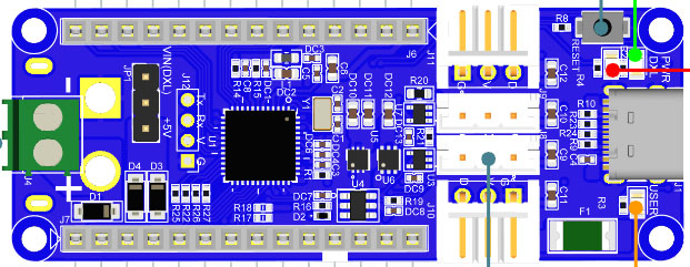
Pin Configuration and Descriptions
The OpenRB-150 features a straightforward pin layout for easy integration. Below is the pin configuration:
Input/Control Pins
| Pin Name | Type | Description |
|---|---|---|
| VCC | Power Input | 5V DC input for logic circuitry |
| GND | Ground | Common ground for the board |
| IN1 | Digital Input | Control signal for Relay 1 |
| IN2 | Digital Input | Control signal for Relay 2 |
| IN3 | Digital Input | Control signal for Relay 3 |
| IN4 | Digital Input | Control signal for Relay 4 |
| UART_RX | UART Input | UART receive pin for serial communication |
| UART_TX | UART Output | UART transmit pin for serial communication |
| I2C_SCL | I2C Input | I2C clock line |
| I2C_SDA | I2C Input/Output | I2C data line |
Output/Relay Pins
| Pin Name | Type | Description |
|---|---|---|
| NO1 | Relay Output | Normally open contact for Relay 1 |
| NC1 | Relay Output | Normally closed contact for Relay 1 |
| COM1 | Relay Output | Common contact for Relay 1 |
| NO2 | Relay Output | Normally open contact for Relay 2 |
| NC2 | Relay Output | Normally closed contact for Relay 2 |
| COM2 | Relay Output | Common contact for Relay 2 |
| NO3 | Relay Output | Normally open contact for Relay 3 |
| NC3 | Relay Output | Normally closed contact for Relay 3 |
| COM3 | Relay Output | Common contact for Relay 3 |
| NO4 | Relay Output | Normally open contact for Relay 4 |
| NC4 | Relay Output | Normally closed contact for Relay 4 |
| COM4 | Relay Output | Common contact for Relay 4 |
Usage Instructions
How to Use the OpenRB-150 in a Circuit
- Power the Board: Connect a 5V DC power supply to the
VCCandGNDpins for the logic circuitry. For the relays, provide a 12V DC power supply. - Connect Control Signals: Use the
IN1toIN4pins to control the relays. These pins can be connected to a microcontroller (e.g., Arduino UNO) or other control devices. - Connect Load: Attach the load (e.g., light, motor) to the relay output terminals (
NO,NC, andCOM) based on your requirements:- Use
NO(Normally Open) if the load should be off by default. - Use
NC(Normally Closed) if the load should be on by default.
- Use
- Control the Relays: Send a HIGH signal (5V) to the input pins (
IN1toIN4) to activate the corresponding relay.
Important Considerations
- Ensure the load connected to the relay does not exceed the rated current and voltage (10A @ 250V AC or 10A @ 30V DC).
- Use proper insulation and safety precautions when working with high-voltage loads.
- Avoid switching inductive loads (e.g., motors) without a flyback diode or snubber circuit to prevent damage to the relays.
Example: Using OpenRB-150 with Arduino UNO
Below is an example of how to control the OpenRB-150 using an Arduino UNO:
// Example: Controlling OpenRB-150 relays with Arduino UNO

// Define relay control pins
#define RELAY1 2  // Connect IN1 to Arduino pin 2
#define RELAY2 3  // Connect IN2 to Arduino pin 3
#define RELAY3 4  // Connect IN3 to Arduino pin 4
#define RELAY4 5  // Connect IN4 to Arduino pin 5

void setup() {
  // Set relay pins as outputs
  pinMode(RELAY1, OUTPUT);
  pinMode(RELAY2, OUTPUT);
  pinMode(RELAY3, OUTPUT);
  pinMode(RELAY4, OUTPUT);

  // Initialize all relays to OFF
  digitalWrite(RELAY1, LOW);
  digitalWrite(RELAY2, LOW);
  digitalWrite(RELAY3, LOW);
  digitalWrite(RELAY4, LOW);
}

void loop() {
  // Turn on Relay 1
  digitalWrite(RELAY1, HIGH);
  delay(1000); // Wait for 1 second

  // Turn off Relay 1 and turn on Relay 2
  digitalWrite(RELAY1, LOW);
  digitalWrite(RELAY2, HIGH);
  delay(1000); // Wait for 1 second

  // Turn off Relay 2 and turn on Relay 3
  digitalWrite(RELAY2, LOW);
  digitalWrite(RELAY3, HIGH);
  delay(1000); // Wait for 1 second

  // Turn off Relay 3 and turn on Relay 4
  digitalWrite(RELAY3, LOW);
  digitalWrite(RELAY4, HIGH);
  delay(1000); // Wait for 1 second

  // Turn off all relays
  digitalWrite(RELAY4, LOW);
  delay(1000); // Wait for 1 second
}
Troubleshooting and FAQs
Common Issues
Relays Not Activating
- Cause: Insufficient power supply to the board.
- Solution: Ensure the
VCCpin is receiving 5V DC and the relay power supply is 12V DC.
Load Not Switching
- Cause: Incorrect wiring of the load to the relay terminals.
- Solution: Verify the load is connected to the correct relay output terminals (
NO,NC, andCOM).
Microcontroller Not Controlling Relays
- Cause: Incorrect signal levels or pin configuration.
- Solution: Ensure the control pins (
IN1toIN4) are receiving a HIGH signal (5V) from the microcontroller.
Relay Clicking Noise
- Cause: Rapid switching or unstable control signals.
- Solution: Check the control signal stability and avoid rapid toggling of the relays.
FAQs
Can the OpenRB-150 handle AC loads? Yes, the relays are rated for up to 250V AC at 10A.
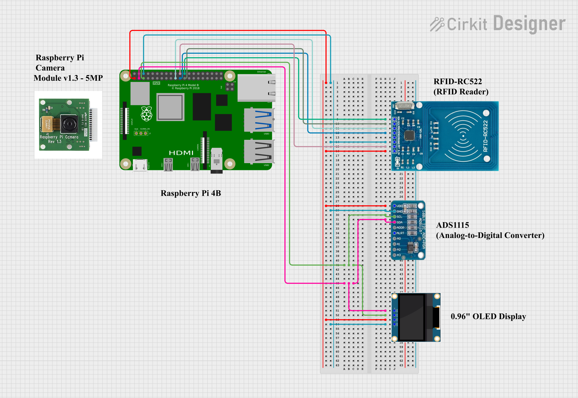
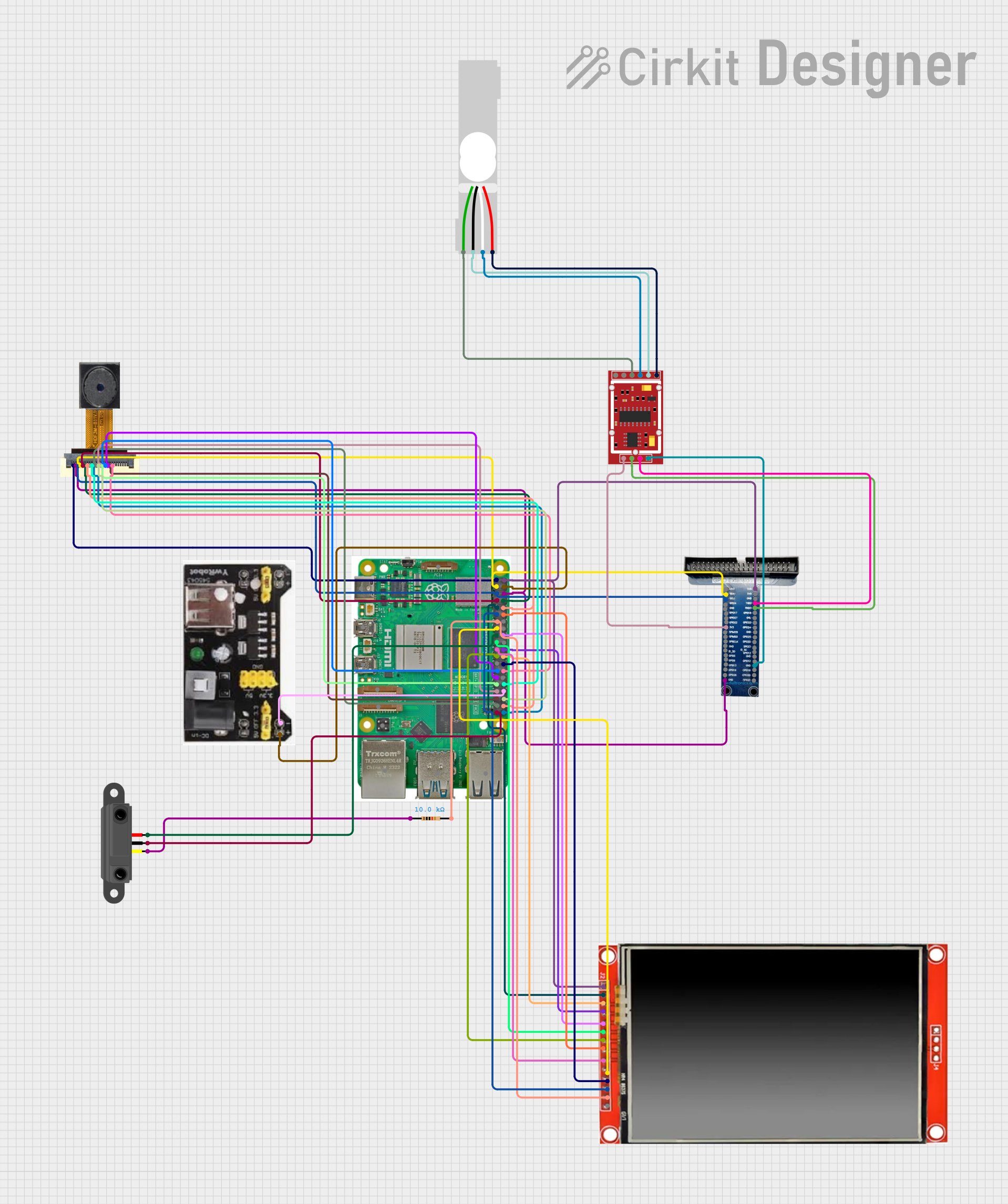
Is the board compatible with Raspberry Pi? Yes, the board can be controlled via GPIO pins on a Raspberry Pi.
Can I use the board for inductive loads like motors? Yes, but you must use a flyback diode or snubber circuit to protect the relays from voltage spikes.
What is the maximum switching frequency of the relays? The relays are mechanical and are not designed for high-frequency switching. Use solid-state relays for high-speed applications.