
How to Use MAGJACK-POE: Examples, Pinouts, and Specs
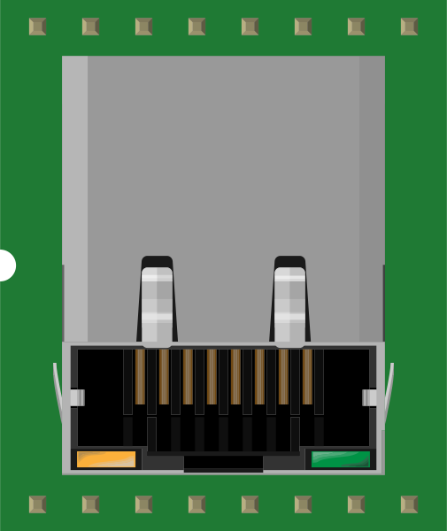
 Design with MAGJACK-POE in Cirkit Designer
Introduction
The MAGJACK-POE is a modular connector designed to integrate Power over Ethernet (PoE) capabilities. This component allows both data and electrical power to be transmitted over a single Ethernet cable, simplifying network infrastructure and reducing the need for separate power supplies. It is widely used in applications such as IP cameras, VoIP phones, wireless access points, and other networked devices that require both power and data connectivity.
By combining Ethernet data transmission with power delivery, the MAGJACK-POE enables efficient and cost-effective solutions for powering remote devices in a variety of environments.
Explore Projects Built with MAGJACK-POE
 Open Project in Cirkit Designer
 Open Project in Cirkit Designer
 Open Project in Cirkit Designer
 Open Project in Cirkit Designer
Explore Projects Built with MAGJACK-POE
Open Project in Cirkit DesignerOpen Project in Cirkit DesignerOpen Project in Cirkit DesignerOpen Project in Cirkit DesignerTechnical Specifications
The MAGJACK-POE is available in various configurations, but the following are typical specifications for a standard model:
Key Technical Details
- Data Transmission Standard: IEEE 802.3 (10/100/1000 Mbps Ethernet)
- PoE Standard Compliance: IEEE 802.3af/at (Type 1 and Type 2)
- Voltage Range: 44V to 57V DC (PoE input)
- Maximum Power Output: Up to 25.5W (PoE+)
- Operating Temperature: -40°C to +85°C
- Insertion Loss: ≤ 1.2 dB (at 100 MHz)
- Return Loss: ≥ 16 dB (at 100 MHz)
- Isolation Voltage: 1500V AC (minimum)
Pin Configuration and Descriptions
The MAGJACK-POE typically features an 8-pin RJ45 connector with integrated magnetics. Below is the pinout for a standard configuration:
| Pin Number | Signal Name | Description |
|---|---|---|
| 1 | TX+ | Transmit Data Positive |
| 2 | TX- | Transmit Data Negative |
| 3 | RX+ | Receive Data Positive |
| 4 | PoE V+ | Positive Power Supply (PoE) |
| 5 | PoE V+ | Positive Power Supply (PoE) |
| 6 | RX- | Receive Data Negative |
| 7 | PoE V- | Negative Power Supply (PoE) |
| 8 | PoE V- | Negative Power Supply (PoE) |
Note: Pins 4, 5, 7, and 8 are used for power delivery in PoE applications, while pins 1, 2, 3, and 6 are used for Ethernet data transmission.
Usage Instructions
How to Use the MAGJACK-POE in a Circuit
- Power Source: Ensure that your power source complies with the PoE standard (IEEE 802.3af/at). A PoE injector or PoE-enabled switch can be used to supply power.
- Data Connection: Connect the MAGJACK-POE to an Ethernet-enabled device using a standard Ethernet cable (Cat5e or higher is recommended for optimal performance).
- PCB Integration: When integrating the MAGJACK-POE into a PCB, ensure proper routing of power and data lines. Use differential pairs for TX and RX signals to minimize noise and signal degradation.
- Magnetics: The integrated magnetics in the MAGJACK-POE provide isolation and signal integrity. No additional external magnetics are required.
Important Considerations and Best Practices
- Power Budget: Verify that the total power consumption of connected devices does not exceed the power budget of your PoE source.
- Cable Length: The maximum cable length for Ethernet with PoE is 100 meters (328 feet). Exceeding this length may result in power loss and degraded data signals.
- Thermal Management: Ensure adequate ventilation or cooling for devices using PoE, as power delivery can generate heat.
- Compliance: Use components and devices that comply with the IEEE 802.3af/at standards to ensure compatibility and safety.
Example: Using MAGJACK-POE with Arduino UNO
To interface the MAGJACK-POE with an Arduino UNO, you can use an Ethernet shield that includes a PoE-enabled RJ45 jack. Below is an example code snippet for setting up a basic web server:
#include <SPI.h>
#include <Ethernet.h>

// MAC address and IP address for the Ethernet shield
byte mac[] = { 0xDE, 0xAD, 0xBE, 0xEF, 0xFE, 0xED };
IPAddress ip(192, 168, 1, 177);

// Initialize the Ethernet server on port 80
EthernetServer server(80);

void setup() {
  // Start the Ethernet connection
  Ethernet.begin(mac, ip);

  // Start the server
  server.begin();
  Serial.begin(9600);
  Serial.println("Server is ready at http://192.168.1.177");
}

void loop() {
  // Listen for incoming clients
  EthernetClient client = server.available();
  if (client) {
    Serial.println("New client connected");
    boolean currentLineIsBlank = true;
    while (client.connected()) {
      if (client.available()) {
        char c = client.read();
        Serial.write(c);

        // If a newline is received, send a response
        if (c == '\n' && currentLineIsBlank) {
          client.println("HTTP/1.1 200 OK");
          client.println("Content-Type: text/html");
          client.println("Connection: close");
          client.println();
          client.println("<!DOCTYPE HTML>");
          client.println("<html>");
          client.println("<h1>Hello from MAGJACK-POE!</h1>");
          client.println("</html>");
          break;
        }
        if (c == '\n') {
          currentLineIsBlank = true;
        } else if (c != '\r') {
          currentLineIsBlank = false;
        }
      }
    }
    // Give the client time to receive the data
    delay(1);
    client.stop();
    Serial.println("Client disconnected");
  }
}
Note: Ensure that your Ethernet shield supports PoE and is properly powered.
Troubleshooting and FAQs
Common Issues
No Power Delivery:
- Cause: The PoE source may not be active or compatible.
- Solution: Verify that the PoE injector or switch is functioning and compliant with IEEE 802.3af/at standards.
Data Transmission Errors:
- Cause: Poor cable quality or excessive cable length.
- Solution: Use high-quality Cat5e or Cat6 cables and ensure the length does not exceed 100 meters.
Overheating:
- Cause: Insufficient ventilation or excessive power draw.
- Solution: Improve airflow around the device and ensure the power budget is not exceeded.
Intermittent Connectivity:
- Cause: Loose connections or damaged pins.
- Solution: Inspect the RJ45 connector and ensure all pins are intact and properly seated.
FAQs
Q: Can the MAGJACK-POE be used with non-PoE devices?
A: Yes, it can transmit data to non-PoE devices, but power delivery will not be utilized.Q: What is the maximum power output of the MAGJACK-POE?
A: The maximum power output is 25.5W when compliant with the IEEE 802.3at (PoE+) standard.Q: Is additional circuitry required for PoE functionality?
A: No, the MAGJACK-POE has integrated magnetics and is designed for direct integration into PoE systems.
By following this documentation, you can effectively integrate and troubleshoot the MAGJACK-POE in your projects.