Cirkit Designer Logo
Cirkit Designer
Your all-in-one circuit design IDE
Home / 
Component Documentation

How to Use usfi voltage regulator: Examples, Pinouts, and Specs

Image of usfi voltage regulator
Cirkit Designer LogoDesign with usfi voltage regulator in Cirkit Designer

Introduction

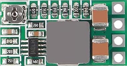
The USFI voltage regulator is an essential electronic component designed to maintain a constant voltage level. It ensures that electronic devices receive a steady voltage despite variations in the input power, which is crucial for the reliable operation of sensitive electronics. Common applications include power supply stabilization, battery charging circuits, and as a safeguard in microcontroller systems, such as those involving an Arduino UNO.

Explore Projects Built with usfi voltage regulator

Use Cirkit Designer to design, explore, and prototype these projects online. Some projects support real-time simulation. Click "Open Project" to start designing instantly!
Battery-Powered LM393-Based Voltage Comparator Circuit with MOSFET Control
Image of cut off charger: A project utilizing usfi voltage regulator in a practical application
This circuit is a power regulation and control system that uses an LM393 comparator to monitor voltage levels and control a MOSFET (IRFZ44N) for switching. It is powered by a 12V battery and a USB power source, and includes various resistors and capacitors for filtering and stabilization.
Cirkit Designer LogoOpen Project in Cirkit Designer
12V UPS System with Dual 18650 Li-ion Battery Backup and Voltage Regulation
Image of Power supply: A project utilizing usfi voltage regulator in a practical application
This circuit is designed to provide an uninterruptible power supply (UPS) system with a 12V DC output. It includes a 12V 5A power supply connected to an AC source through a toggle switch, which charges a pair of 18650 Li-ion batteries via a voltage regulator (XL4016). The UPS module ensures a continuous power supply to the load by switching between the power supply and the battery bank.
Cirkit Designer LogoOpen Project in Cirkit Designer
Battery-Powered UPS with Step-Down Buck Converter and BMS
Image of Mini ups: A project utilizing usfi voltage regulator in a practical application
This circuit is a power management system that steps down a 240V AC input to a lower DC voltage using a buck converter, which then powers a 40W UPS. The UPS is controlled by a rocker switch and is backed up by a battery management system (BMS) connected to three 3.7V batteries in series, ensuring continuous power supply.
Cirkit Designer LogoOpen Project in Cirkit Designer
AC to DC Power Supply with Voltage Regulation and Overcurrent Protection
Image of PENGATUR VOLTAN: A project utilizing usfi voltage regulator in a practical application
This circuit appears to be a power supply unit with a transformer for stepping down voltage, a bridge rectifier for converting AC to DC, and a voltage regulator for stabilizing the output voltage. It includes a Zener diode for overvoltage protection, capacitors for smoothing out ripples in the DC supply, and a fuse for overcurrent protection. A toggle switch and a rocker switch are used to control the power flow, and there is an LED indicator connected through resistors, likely for power-on indication.
Cirkit Designer LogoOpen Project in Cirkit Designer

Explore Projects Built with usfi voltage regulator

Use Cirkit Designer to design, explore, and prototype these projects online. Some projects support real-time simulation. Click "Open Project" to start designing instantly!
Image of cut off charger: A project utilizing usfi voltage regulator in a practical application
Battery-Powered LM393-Based Voltage Comparator Circuit with MOSFET Control
This circuit is a power regulation and control system that uses an LM393 comparator to monitor voltage levels and control a MOSFET (IRFZ44N) for switching. It is powered by a 12V battery and a USB power source, and includes various resistors and capacitors for filtering and stabilization.
Cirkit Designer LogoOpen Project in Cirkit Designer
Image of Power supply: A project utilizing usfi voltage regulator in a practical application
12V UPS System with Dual 18650 Li-ion Battery Backup and Voltage Regulation
This circuit is designed to provide an uninterruptible power supply (UPS) system with a 12V DC output. It includes a 12V 5A power supply connected to an AC source through a toggle switch, which charges a pair of 18650 Li-ion batteries via a voltage regulator (XL4016). The UPS module ensures a continuous power supply to the load by switching between the power supply and the battery bank.
Cirkit Designer LogoOpen Project in Cirkit Designer
Image of Mini ups: A project utilizing usfi voltage regulator in a practical application
Battery-Powered UPS with Step-Down Buck Converter and BMS
This circuit is a power management system that steps down a 240V AC input to a lower DC voltage using a buck converter, which then powers a 40W UPS. The UPS is controlled by a rocker switch and is backed up by a battery management system (BMS) connected to three 3.7V batteries in series, ensuring continuous power supply.
Cirkit Designer LogoOpen Project in Cirkit Designer
Image of PENGATUR VOLTAN: A project utilizing usfi voltage regulator in a practical application
AC to DC Power Supply with Voltage Regulation and Overcurrent Protection
This circuit appears to be a power supply unit with a transformer for stepping down voltage, a bridge rectifier for converting AC to DC, and a voltage regulator for stabilizing the output voltage. It includes a Zener diode for overvoltage protection, capacitors for smoothing out ripples in the DC supply, and a fuse for overcurrent protection. A toggle switch and a rocker switch are used to control the power flow, and there is an LED indicator connected through resistors, likely for power-on indication.
Cirkit Designer LogoOpen Project in Cirkit Designer

Technical Specifications

Key Technical Details

  • Input Voltage Range: The range of voltage the regulator can accept.
  • Output Voltage: The stable voltage the regulator provides.
  • Output Current: Maximum current the regulator can supply.
  • Quiescent Current: The current consumed by the regulator when not supplying load.
  • Thermal Shutdown: The temperature at which the regulator will shut down to prevent damage.
  • Package Type: Physical form factor of the regulator.

Pin Configuration and Descriptions

Pin Number Name Description
1 VIN Input voltage to the regulator. Must be within the specified range.
2 GND Ground reference for the circuit.
3 VOUT Regulated output voltage provided to the load.

Usage Instructions

Incorporating into a Circuit

  1. Input Connection: Connect the input voltage source to the VIN pin, ensuring it falls within the specified input voltage range.
  2. Grounding: Connect the GND pin to the common ground of your circuit.
  3. Output Load: Connect the load to the VOUT pin. Ensure the load does not exceed the maximum output current rating.

Best Practices

  • Heat Dissipation: If the regulator is expected to dissipate significant heat, attach an appropriate heatsink.
  • Capacitors: Place a capacitor close to the input and output pins to smooth out any voltage spikes and improve transient response.
  • Thermal Considerations: Keep the regulator away from heat-sensitive components and provide adequate ventilation.

Example Connection with Arduino UNO

// No specific code is required for a basic voltage regulator setup.
// However, ensure that the regulated voltage is compatible with the Arduino's requirements.

void setup() {
  // Initialize digital pins, serial communication, etc. as needed.
}

void loop() {
  // Your code here to perform tasks.
}

Troubleshooting and FAQs

Common Issues

  • Voltage Drop: If the output voltage is lower than expected, check the input voltage and the load current to ensure they are within specifications.
  • Overheating: If the regulator is too hot, reduce the load current, improve heat dissipation, or check for short circuits.
  • No Output: Verify connections, ensure the input voltage is present and within range, and check for any signs of physical damage to the regulator.

FAQs

Q: Can I use the USFI voltage regulator to step up voltage? A: No, this regulator is designed to maintain a steady output voltage and cannot increase voltage levels.

Q: What happens if the input voltage drops below the minimum required? A: The regulator may not be able to maintain the output voltage, leading to a drop in voltage supplied to the load.

Q: Is it necessary to use capacitors with the USFI voltage regulator? A: While not always mandatory, using capacitors is recommended to ensure stability and reduce noise in the output voltage.

Q: How do I choose the right heatsink for my voltage regulator? A: Calculate the power dissipation and choose a heatsink with an appropriate thermal resistance rating to keep the regulator within its safe operating temperature range.

For further assistance or more detailed inquiries, please refer to the manufacturer's datasheet or contact technical support.