Cirkit Designer Logo
Cirkit Designer
Your all-in-one circuit design IDE
Home / 
Component Documentation

How to Use 12v to 5v Step Down Power Converter: Examples, Pinouts, and Specs

Image of 12v to 5v Step Down Power Converter
Cirkit Designer LogoDesign with 12v to 5v Step Down Power Converter in Cirkit Designer

Introduction

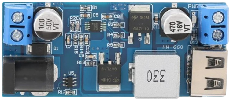
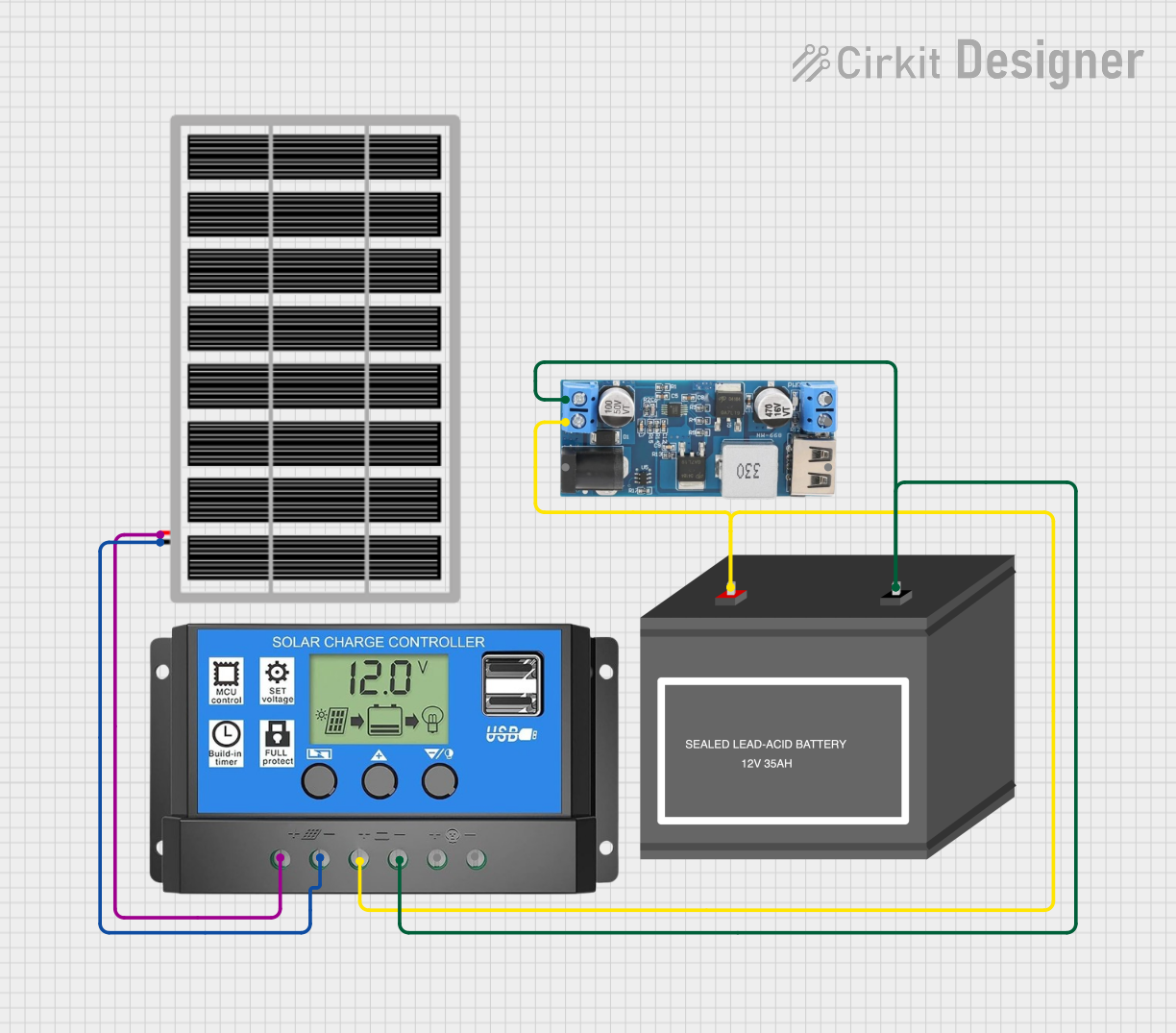
A 12V to 5V step-down power converter is an electronic device designed to convert a higher input voltage of 12 volts DC to a stable lower output voltage of 5 volts DC. This type of converter is essential in applications where the power supply voltage is higher than what the electronic components require. Common use cases include automotive electronics, where the car battery provides 12V, but the electronic circuits, such as sensors, microcontrollers, and other digital devices, operate at 5V.

Explore Projects Built with 12v to 5v Step Down Power Converter

Use Cirkit Designer to design, explore, and prototype these projects online. Some projects support real-time simulation. Click "Open Project" to start designing instantly!
Solar-Powered Battery Charging System with 12V to 5V Step-Down Converter
Image of power circuit: A project utilizing 12v to 5v Step Down Power Converter in a practical application
This circuit is designed to harness solar energy to charge a 12V battery using a solar charge controller. The stored energy in the battery is then stepped down to 5V using a step-down power converter, providing a stable 5V output for other devices.
Cirkit Designer LogoOpen Project in Cirkit Designer
Arduino Mega 2560-Based Robotic System with Stepper Motors and IR Sensors
Image of FYP: A project utilizing 12v to 5v Step Down Power Converter in a practical application
This circuit is a control system powered by a 12V to 5V step-down converter, featuring an Arduino Mega 2560 microcontroller that interfaces with various sensors (IR sensors, limit switch), actuators (servos, stepper motors), and a 20x4 LCD display. The system is designed to monitor inputs from sensors and control outputs to motors and display information, suitable for applications like automation or robotics.
Cirkit Designer LogoOpen Project in Cirkit Designer
USB Power Supply with Overcurrent Protection
Image of USB Charging port: A project utilizing 12v to 5v Step Down Power Converter in a practical application
This circuit is designed to step down voltage from a 12V battery to a lower voltage suitable for USB devices. It includes a buck converter connected to the battery through a fuse and fuse holder for overcurrent protection. The output of the buck converter is connected to a USB female port, providing a regulated power supply for USB-powered devices.
Cirkit Designer LogoOpen Project in Cirkit Designer
Battery-Powered DC Generator with XL4015 Buck Converter
Image of conveyor: A project utilizing 12v to 5v Step Down Power Converter in a practical application
This circuit consists of a 12V battery connected to a rocker switch, which controls the input to an XL4015 DC Buck Step-down converter. The converter steps down the voltage to power a DC generator, with the generator's output connected back to the converter to form a feedback loop.
Cirkit Designer LogoOpen Project in Cirkit Designer

Explore Projects Built with 12v to 5v Step Down Power Converter

Use Cirkit Designer to design, explore, and prototype these projects online. Some projects support real-time simulation. Click "Open Project" to start designing instantly!
Image of power circuit: A project utilizing 12v to 5v Step Down Power Converter in a practical application
Solar-Powered Battery Charging System with 12V to 5V Step-Down Converter
This circuit is designed to harness solar energy to charge a 12V battery using a solar charge controller. The stored energy in the battery is then stepped down to 5V using a step-down power converter, providing a stable 5V output for other devices.
Cirkit Designer LogoOpen Project in Cirkit Designer
Image of FYP: A project utilizing 12v to 5v Step Down Power Converter in a practical application
Arduino Mega 2560-Based Robotic System with Stepper Motors and IR Sensors
This circuit is a control system powered by a 12V to 5V step-down converter, featuring an Arduino Mega 2560 microcontroller that interfaces with various sensors (IR sensors, limit switch), actuators (servos, stepper motors), and a 20x4 LCD display. The system is designed to monitor inputs from sensors and control outputs to motors and display information, suitable for applications like automation or robotics.
Cirkit Designer LogoOpen Project in Cirkit Designer
Image of USB Charging port: A project utilizing 12v to 5v Step Down Power Converter in a practical application
USB Power Supply with Overcurrent Protection
This circuit is designed to step down voltage from a 12V battery to a lower voltage suitable for USB devices. It includes a buck converter connected to the battery through a fuse and fuse holder for overcurrent protection. The output of the buck converter is connected to a USB female port, providing a regulated power supply for USB-powered devices.
Cirkit Designer LogoOpen Project in Cirkit Designer
Image of conveyor: A project utilizing 12v to 5v Step Down Power Converter in a practical application
Battery-Powered DC Generator with XL4015 Buck Converter
This circuit consists of a 12V battery connected to a rocker switch, which controls the input to an XL4015 DC Buck Step-down converter. The converter steps down the voltage to power a DC generator, with the generator's output connected back to the converter to form a feedback loop.
Cirkit Designer LogoOpen Project in Cirkit Designer

Technical Specifications

Key Technical Details

  • Input Voltage: 12V DC
  • Output Voltage: 5V DC
  • Maximum Output Current: Specified by the manufacturer (e.g., 1A, 2A, 3A)
  • Conversion Efficiency: Typically >90%
  • Operating Temperature Range: Specified by the manufacturer (e.g., -40°C to +85°C)

Pin Configuration and Descriptions

Pin Number Name Description
1 VIN Input voltage (12V DC)
2 GND Ground connection
3 VOUT Output voltage (5V DC)
4 GND Ground connection for the output side

Usage Instructions

How to Use the Component in a Circuit

  1. Connecting Input Power:

    • Connect the 12V power source to the VIN and GND pins of the converter.
    • Ensure that the polarity is correct to prevent damage to the converter.
  2. Connecting Output Power:

    • Connect the device that requires 5V to the VOUT and GND pins.
    • Ensure that the current draw of the device does not exceed the maximum output current of the converter.
  3. Mounting the Converter:

    • Secure the converter to your project using appropriate mounting techniques to prevent movement and potential short circuits.

Important Considerations and Best Practices

  • Heat Dissipation: Depending on the load and conversion efficiency, the converter may generate heat. Ensure adequate ventilation or add a heatsink if necessary.
  • Overcurrent Protection: Incorporate a fuse or a current limiting device on the input side to protect against overcurrent conditions.
  • Voltage Regulation: Verify that the output voltage remains stable under varying load conditions to ensure the safety of downstream components.
  • Isolation: If the application requires, use an isolated step-down converter to prevent ground loops and reduce noise.

Troubleshooting and FAQs

Common Issues

  • Output Voltage is Too Low or Unstable:

    • Check if the input voltage is stable and within the specified range.
    • Ensure that the output load does not exceed the maximum current rating of the converter.
    • Verify that there are no short circuits on the output side.
  • Converter is Overheating:

    • Reduce the load on the converter if it exceeds the recommended specifications.
    • Improve ventilation or add a heatsink to the converter.
  • No Output Voltage:

    • Check all connections for proper contact and correct polarity.
    • Inspect the converter for any visible damage or signs of component failure.
    • Ensure that the input voltage is present and within the specified range.

FAQs

Q: Can I use this converter to power an Arduino UNO? A: Yes, an Arduino UNO can be powered with 5V, and this converter is suitable for that purpose.

Q: Is it possible to adjust the output voltage? A: Standard 12V to 5V converters have a fixed output. However, some models come with an adjustable output feature. Check the product specifications for this functionality.

Q: How do I know if the converter is working correctly? A: Measure the output voltage with a multimeter. It should be close to 5V if the converter is functioning properly.

Example Arduino UNO Connection Code

// No specific code is required for the power converter itself, as it is a passive component.
// However, here is an example of how to set up a simple LED circuit powered by the converter.

void setup() {
  pinMode(LED_BUILTIN, OUTPUT); // Set the built-in LED as an output
}

void loop() {
  digitalWrite(LED_BUILTIN, HIGH); // Turn on the LED
  delay(1000);                     // Wait for a second
  digitalWrite(LED_BUILTIN, LOW);  // Turn off the LED
  delay(1000);                     // Wait for a second
}

// Note: The Arduino UNO's built-in LED is connected to pin 13 and can be used
// directly without an external LED for this example. If using an external LED,
// ensure it is connected with a suitable current-limiting resistor.

Remember to connect the 5V output from the step-down converter to the 5V pin on the Arduino UNO and the ground from the converter to one of the GND pins on the Arduino.