How to Use IMPACT SENSOR: Examples, Pinouts, and Specs
Introduction
The Impact Sensor is a device designed to detect and measure the force or impact of an object. It is commonly used in applications where monitoring physical collisions or vibrations is critical. These sensors are widely utilized in safety systems, automotive crash detection, robotics, and industrial machinery to trigger responses or record data upon impact. Their ability to provide real-time feedback makes them essential in systems requiring high reliability and precision.
Explore Projects Built with IMPACT SENSOR
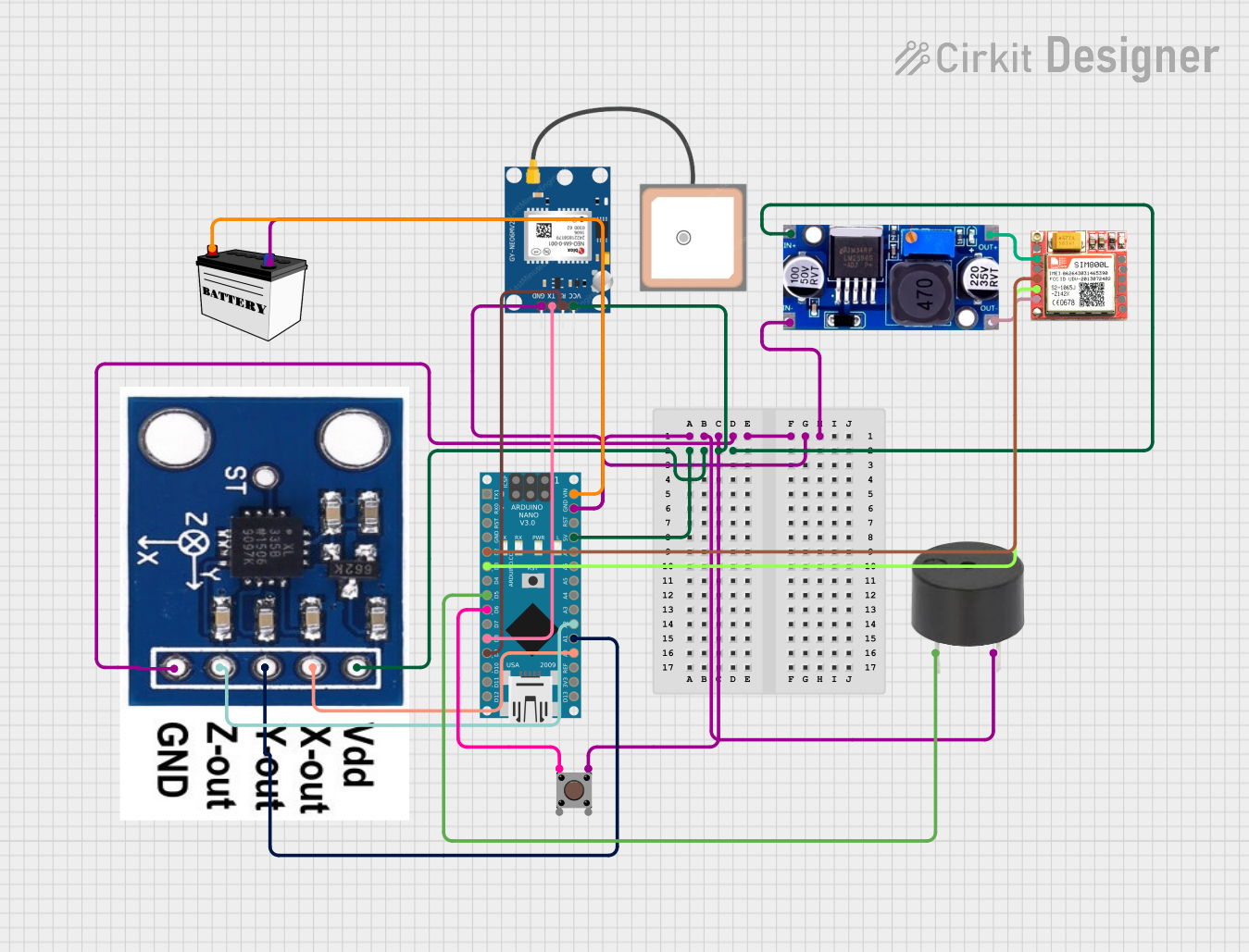
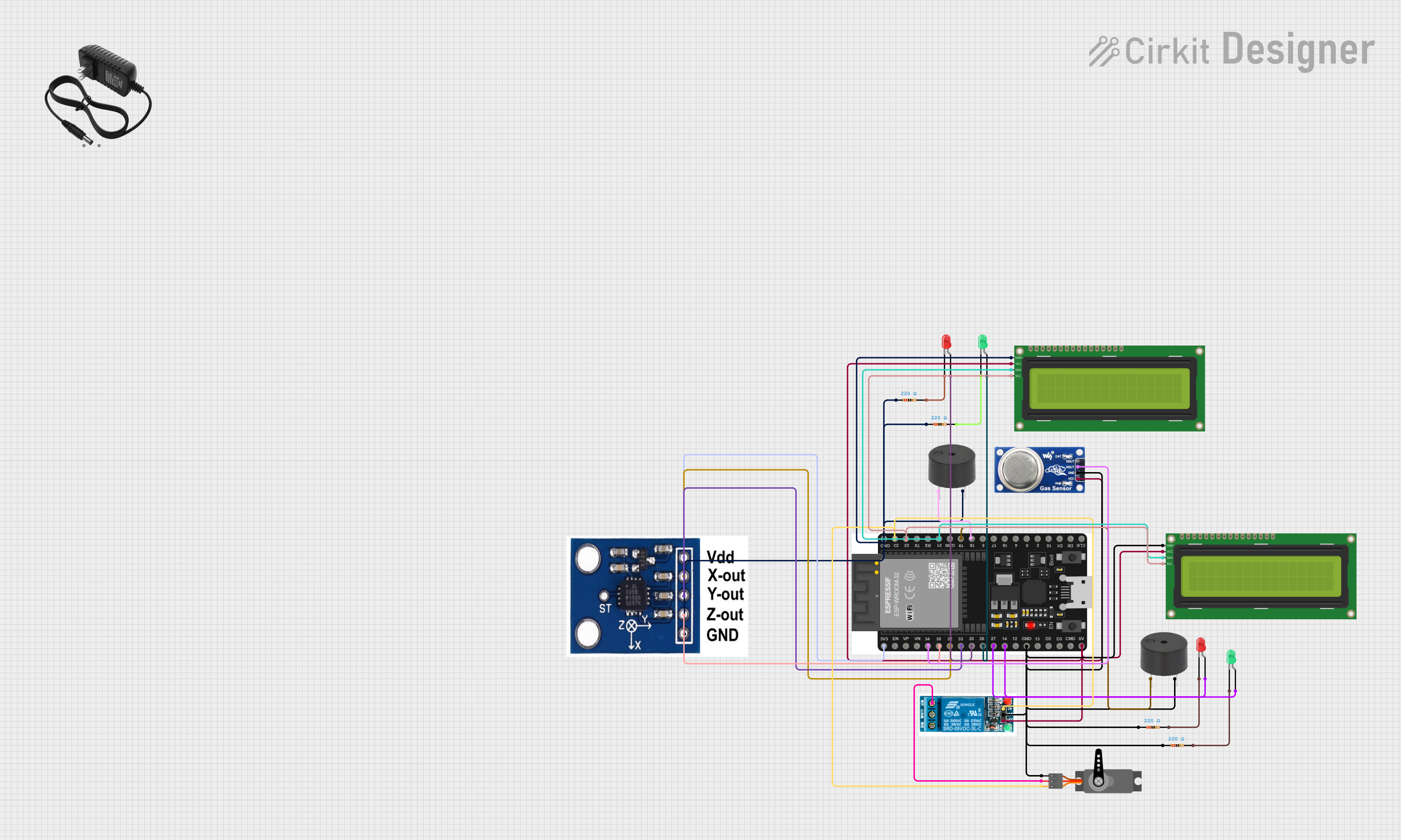
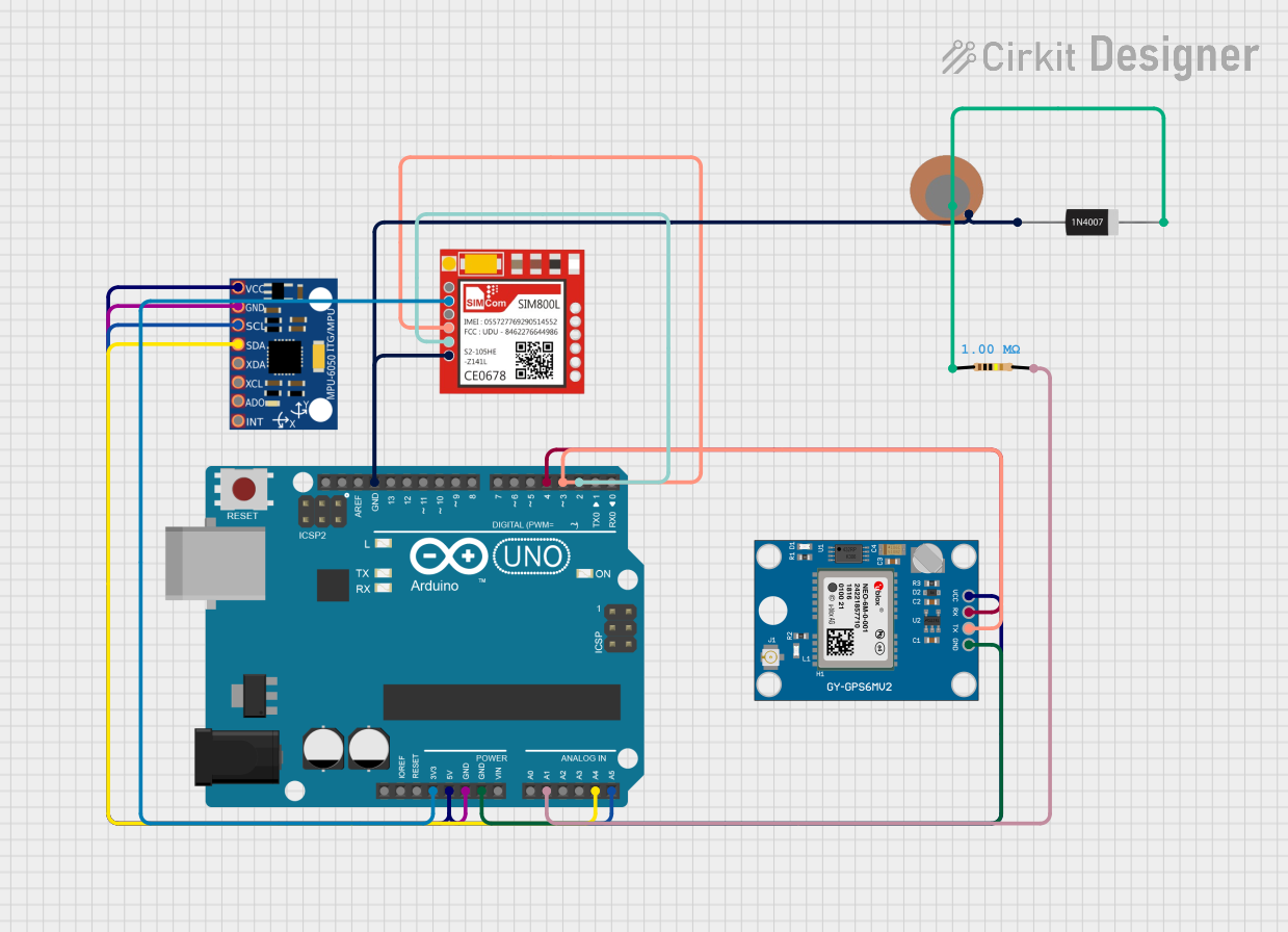

Explore Projects Built with IMPACT SENSOR
Technical Specifications
The following table outlines the key technical details of a typical impact sensor:
| Parameter | Value |
|---|---|
| Operating Voltage | 3.3V to 5V |
| Output Signal | Digital or Analog (depending on model) |
| Sensitivity Range | 1g to 100g (varies by model) |
| Response Time | < 1 ms |
| Operating Temperature | -20°C to 70°C |
| Dimensions | Varies (e.g., 10mm x 10mm x 5mm) |
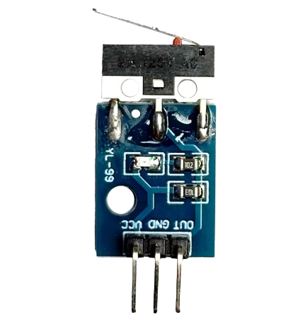
Pin Configuration and Descriptions
Below is the pin configuration for a typical 3-pin impact sensor:
| Pin | Name | Description |
|---|---|---|
| 1 | VCC | Power supply pin (3.3V to 5V) |
| 2 | GND | Ground connection |
| 3 | OUT | Output signal pin (Digital HIGH/LOW or Analog voltage) |
Usage Instructions
How to Use the Impact Sensor in a Circuit
- Power the Sensor: Connect the
VCCpin to a 3.3V or 5V power source and theGNDpin to the ground of your circuit. - Connect the Output: Attach the
OUTpin to a microcontroller's input pin (e.g., Arduino) or an external monitoring system. - Read the Signal: Depending on the sensor type:
- For digital sensors, the
OUTpin will output a HIGH signal when an impact is detected. - For analog sensors, the
OUTpin will provide a voltage proportional to the impact force.
- For digital sensors, the
Important Considerations and Best Practices
- Mounting: Secure the sensor firmly to avoid false readings caused by vibrations or loose connections.
- Debouncing: For digital sensors, implement software debouncing to filter out noise or unintended triggers.
- Voltage Compatibility: Ensure the sensor's operating voltage matches your circuit to prevent damage.
- Calibration: For analog sensors, calibrate the output to match the expected impact range for your application.
Example: Connecting to an Arduino UNO
Below is an example of how to use a digital impact sensor with an Arduino UNO:
// Define the pin connected to the sensor's output
const int impactSensorPin = 2; // Digital pin 2
const int ledPin = 13;         // Built-in LED pin for indication

void setup() {
  pinMode(impactSensorPin, INPUT); // Set sensor pin as input
  pinMode(ledPin, OUTPUT);         // Set LED pin as output
  Serial.begin(9600);              // Initialize serial communication
}

void loop() {
  int sensorState = digitalRead(impactSensorPin); // Read sensor state

  if (sensorState == HIGH) {
    // If impact is detected, turn on the LED and print a message
    digitalWrite(ledPin, HIGH);
    Serial.println("Impact detected!");
  } else {
    // If no impact, turn off the LED
    digitalWrite(ledPin, LOW);
  }

  delay(100); // Small delay to stabilize readings
}
Troubleshooting and FAQs
Common Issues and Solutions
Sensor Not Responding
- Cause: Incorrect wiring or insufficient power supply.
- Solution: Double-check the connections and ensure the power supply matches the sensor's requirements.
False Triggers
- Cause: Environmental vibrations or electrical noise.
- Solution: Use software debouncing and ensure the sensor is securely mounted.
Weak or No Output Signal
- Cause: Impact force is below the sensor's sensitivity threshold.
- Solution: Verify the sensor's sensitivity range and ensure it matches your application.
Output Signal Stuck HIGH or LOW
- Cause: Faulty sensor or damaged components.
- Solution: Test the sensor with a multimeter or replace it if necessary.
FAQs
Q: Can I use the impact sensor with a 12V system?
A: No, most impact sensors operate within a 3.3V to 5V range. Use a voltage regulator if your system operates at 12V.
Q: How do I increase the sensitivity of the sensor?
A: Sensitivity is typically fixed by the manufacturer. If higher sensitivity is required, consider using a different sensor model with a lower threshold.
Q: Can the sensor detect continuous vibrations?
A: Some impact sensors can detect continuous vibrations, but they are primarily designed for discrete impacts. For vibration monitoring, consider using an accelerometer.
Q: Is the sensor waterproof?
A: Most impact sensors are not waterproof. If used in wet environments, ensure proper sealing or use a waterproof enclosure.