
How to Use AMS1117 3.3V: Examples, Pinouts, and Specs
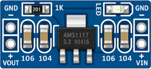
 Design with AMS1117 3.3V in Cirkit Designer
Introduction
The AMS1117 3.3V is a low dropout (LDO) voltage regulator designed to provide a stable output voltage of 3.3 volts. Manufactured by Arduino, this component is widely used in power supply circuits to step down higher input voltages to a regulated 3.3V output. Its compact design and reliable performance make it ideal for powering microcontrollers, sensors, and other low-voltage electronic devices.
Explore Projects Built with AMS1117 3.3V
 Open Project in Cirkit Designer
 Open Project in Cirkit Designer
 Open Project in Cirkit Designer
 Open Project in Cirkit Designer
Explore Projects Built with AMS1117 3.3V
Open Project in Cirkit DesignerOpen Project in Cirkit DesignerOpen Project in Cirkit DesignerOpen Project in Cirkit DesignerCommon Applications
- Powering 3.3V microcontrollers (e.g., ESP8266, ESP32)
- Voltage regulation in battery-powered devices
- Supplying stable power to sensors and modules
- General-purpose voltage regulation in embedded systems
Technical Specifications
The AMS1117 3.3V is designed to operate efficiently in a variety of electronic circuits. Below are its key technical details:
| Parameter | Value |
|---|---|
| Manufacturer | Arduino |
| Part ID | AMS1117 3.3V |
| Output Voltage | 3.3V |
| Input Voltage Range | 4.5V to 15V |
| Dropout Voltage | 1.1V (typical at 1A load) |
| Maximum Output Current | 1A |
| Quiescent Current | 5mA (typical) |
| Operating Temperature | -40°C to +125°C |
| Package Type | SOT-223 |
Pin Configuration
The AMS1117 3.3V has three pins, as described in the table below:
| Pin Number | Pin Name | Description |
|---|---|---|
| 1 | Adjust/GND | Ground (GND) or adjustment pin for fixed output |
| 2 | Vout | Regulated 3.3V output voltage |
| 3 | Vin | Input voltage (4.5V to 15V) |
Usage Instructions
How to Use the AMS1117 3.3V in a Circuit
- Input Voltage: Connect a DC voltage source (4.5V to 15V) to the
Vinpin. Ensure the input voltage is at least 1.1V higher than the desired 3.3V output to maintain proper regulation. - Output Voltage: Connect the load to the
Voutpin. The output voltage will be regulated to 3.3V. - Ground Connection: Connect the
Adjust/GNDpin to the ground of the circuit. - Capacitors: For stable operation, use the following capacitors:
- A 10µF electrolytic capacitor on the input (between
VinandGND). - A 10µF electrolytic capacitor on the output (between
VoutandGND).
- A 10µF electrolytic capacitor on the input (between
Important Considerations
- Heat Dissipation: The AMS1117 3.3V can generate heat under high current loads. Use a heatsink or ensure proper ventilation if the current exceeds 500mA.
- Input Voltage Range: Do not exceed the maximum input voltage of 15V to avoid damaging the regulator.
- Load Current: Ensure the load does not draw more than 1A, as this is the maximum output current rating.
Example: Using AMS1117 3.3V with Arduino UNO
The AMS1117 3.3V can be used to power 3.3V devices from a 5V Arduino UNO. Below is an example circuit and code to interface an ESP8266 module with the Arduino UNO using the AMS1117 3.3V.
Circuit Diagram
- Connect the Arduino UNO's 5V pin to the
Vinpin of the AMS1117 3.3V. - Connect the
Voutpin of the AMS1117 to the VCC pin of the ESP8266. - Connect the
GNDpin of the AMS1117 to the ground of both the Arduino UNO and the ESP8266.
Arduino Code Example
// Example code to communicate with an ESP8266 module powered by AMS1117 3.3V
#include <SoftwareSerial.h>

// Define RX and TX pins for ESP8266 communication
SoftwareSerial esp8266(2, 3); // RX = Pin 2, TX = Pin 3

void setup() {
  Serial.begin(9600); // Initialize Serial Monitor
  esp8266.begin(9600); // Initialize ESP8266 communication

  Serial.println("Initializing ESP8266...");
  esp8266.println("AT"); // Send AT command to check communication
}

void loop() {
  // Check for data from ESP8266
  if (esp8266.available()) {
    String response = esp8266.readString();
    Serial.println("ESP8266 Response: " + response);
  }

  // Check for data from Serial Monitor
  if (Serial.available()) {
    String command = Serial.readString();
    esp8266.println(command); // Send command to ESP8266
  }
}
Troubleshooting and FAQs
Common Issues
No Output Voltage
- Cause: Insufficient input voltage.
- Solution: Ensure the input voltage is at least 4.5V and 1.1V higher than the output voltage.
Overheating
- Cause: High current load or inadequate heat dissipation.
- Solution: Use a heatsink or reduce the load current.
Unstable Output Voltage
- Cause: Missing or insufficient capacitors.
- Solution: Add a 10µF capacitor to both the input and output pins.
Damaged Regulator
- Cause: Input voltage exceeds 15V or output current exceeds 1A.
- Solution: Replace the regulator and ensure input/output limits are not exceeded.
FAQs
Q1: Can I use the AMS1117 3.3V to power a Raspberry Pi?
A1: No, the AMS1117 3.3V cannot supply enough current for a Raspberry Pi, which typically requires more than 1A.
Q2: What happens if I don't use capacitors?
A2: The output voltage may become unstable, leading to erratic behavior in connected devices.
Q3: Can I use the AMS1117 3.3V with a 12V input?
A3: Yes, as long as the input voltage does not exceed 15V and the current load is within limits. However, ensure proper heat dissipation.