Cirkit Designer Logo
Cirkit Designer
Your all-in-one circuit design IDE
Home / 
Component Documentation

How to Use Antenna GPS Embedded SMA: Examples, Pinouts, and Specs
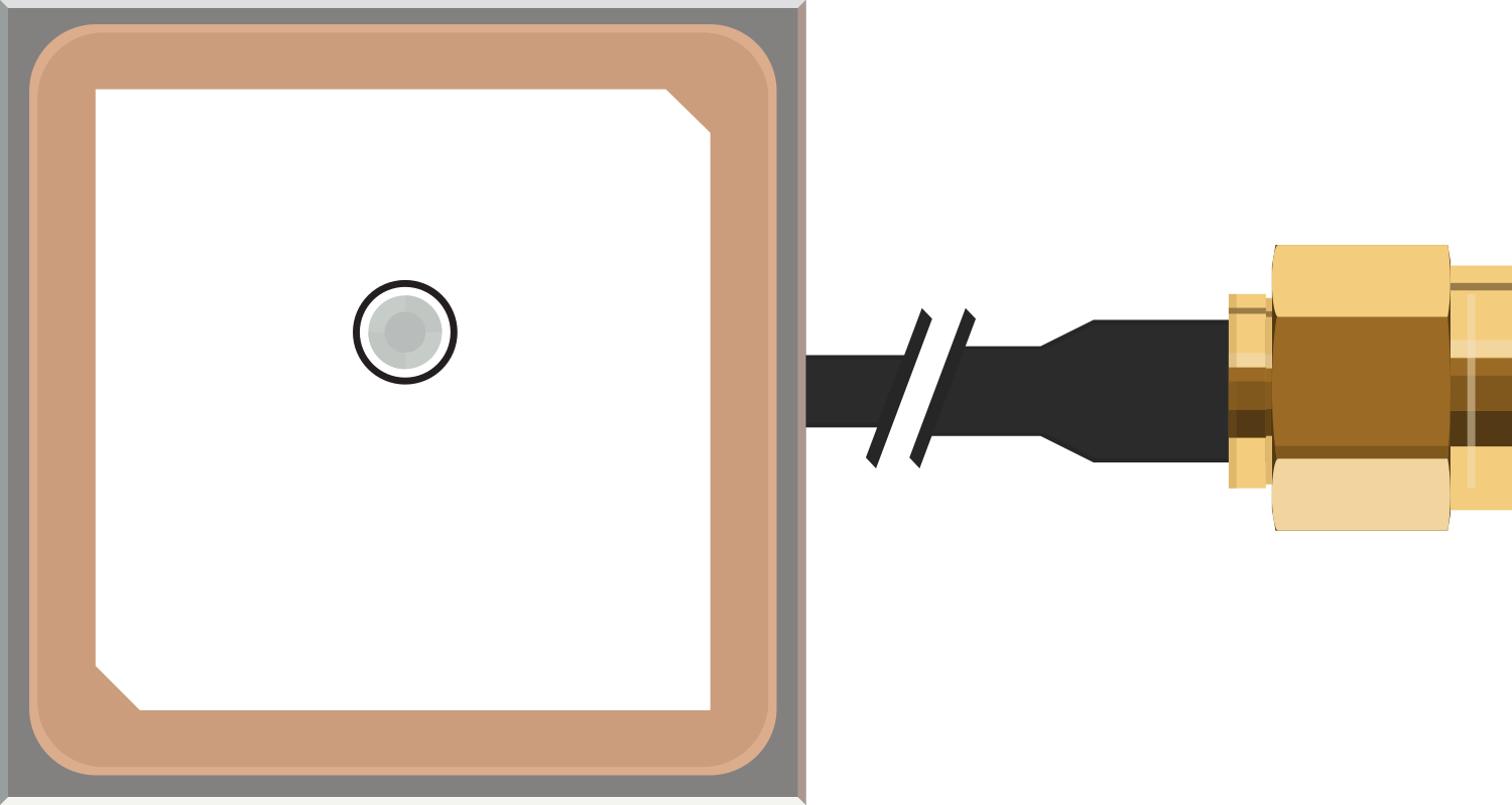

Image of Antenna GPS Embedded SMA
Cirkit Designer LogoDesign with Antenna GPS Embedded SMA in Cirkit Designer

Introduction

The Antenna GPS Embedded SMA is a compact and efficient GPS antenna designed for embedded applications. It features an SMA connector, which ensures easy integration into a wide range of devices. This antenna is optimized for accurate positioning and navigation, making it ideal for applications such as GPS tracking, IoT devices, automotive systems, and portable navigation units.

Common applications include:

  • GPS-enabled IoT devices
  • Vehicle tracking systems
  • Portable navigation devices
  • Drones and UAVs
  • Smart agriculture equipment

Explore Projects Built with Antenna GPS Embedded SMA
Use Cirkit Designer to design, explore, and prototype these projects online. Some projects support real-time simulation. Click "Open Project" to start designing instantly!
Arduino Mega 2560 and UHF RFID-Based Animal Tag Detection System with GPS
Image of  Game Play Design: A project utilizing Antenna GPS Embedded SMA in a practical application
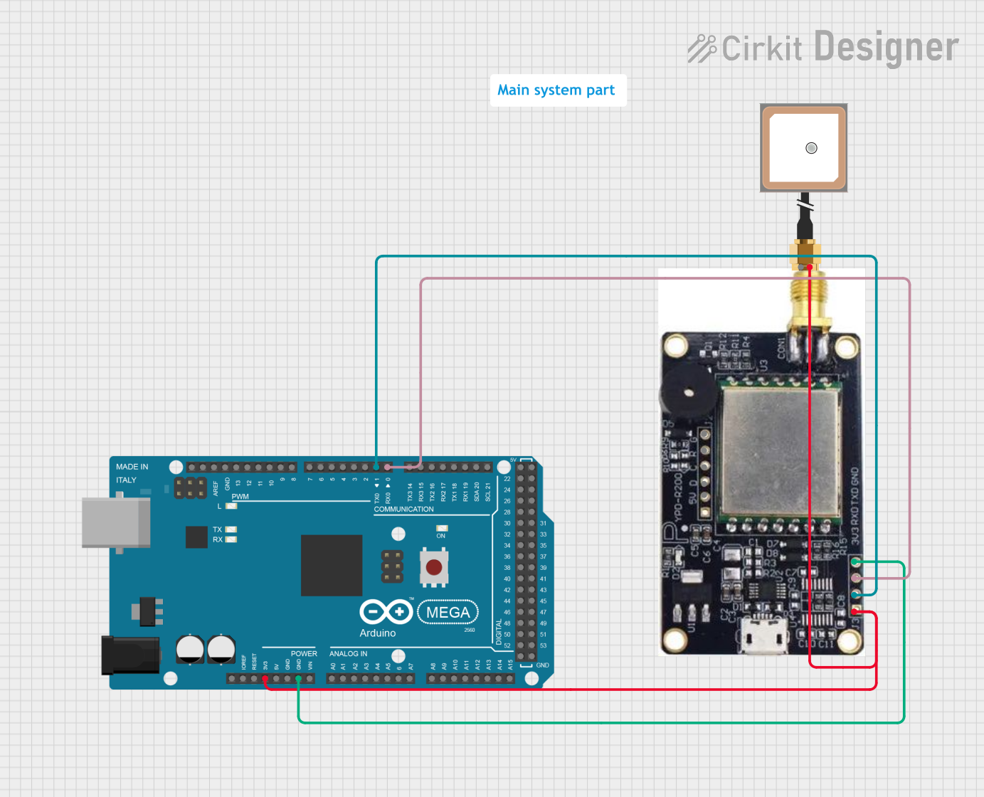
This circuit integrates an Arduino Mega 2560 with a UHF RFID module and a GPS antenna. The Arduino reads RFID tag data from the UHF RFID module and processes it to detect specific tags, while the GPS antenna is powered but not actively used in the provided code.
Cirkit Designer LogoOpen Project in Cirkit Designer
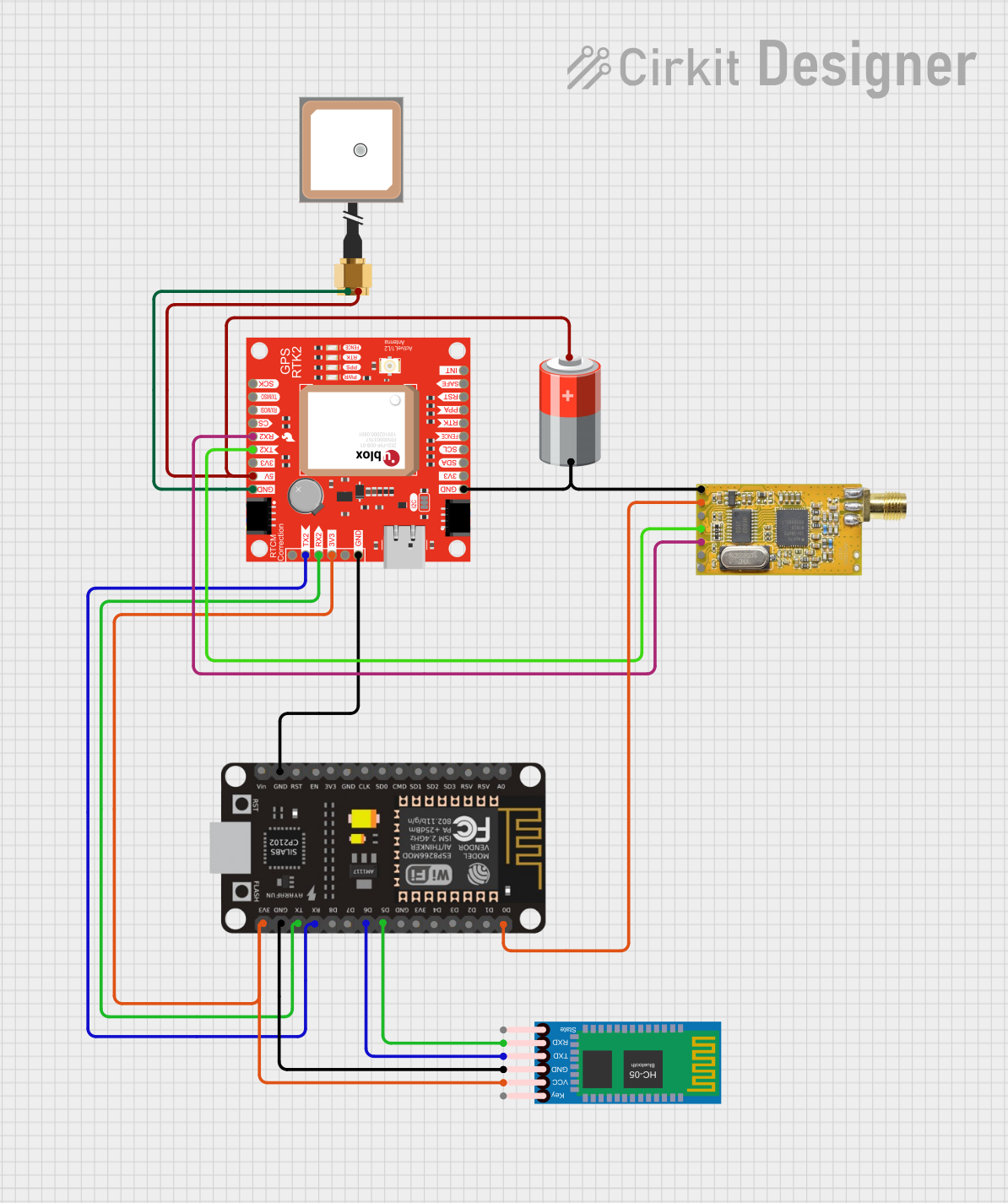
ESP8266 and GPS-RTK2 Based Real-Time GPS Tracker with Bluetooth and APC220 Communication
Image of PANDURTKU0001_1: A project utilizing Antenna GPS Embedded SMA in a practical application
This circuit integrates a GPS module, an ESP8266 microcontroller, a Bluetooth module, and an APC220 RF module to collect and transmit GPS data. The ESP8266 reads GPS data from the SparkFun Qwiic GPS-RTK2 module and can communicate this data via Bluetooth and RF transmission. The system is powered by a 5V battery and includes an embedded GPS antenna for signal reception.
Cirkit Designer LogoOpen Project in Cirkit Designer
Satellite Compass and Network-Integrated GPS Data Processing System
Image of GPS 시스템 측정 구성도_241016: A project utilizing Antenna GPS Embedded SMA in a practical application
This circuit comprises a satellite compass, a mini PC, two GPS antennas, power supplies, a network switch, media converters, and an atomic rubidium clock. The satellite compass is powered by a triple output DC power supply and interfaces with an RS232 splitter for 1PPS signals. The mini PCs are connected to the USRP B200 devices via USB for data and power, and to media converters via Ethernet, which in turn connect to a network switch using fiber optic links. The antennas are connected to the USRP B200s through RF directional couplers, and the atomic clock provides a 1PPS input to the RS232 splitter.
Cirkit Designer LogoOpen Project in Cirkit Designer
Satellite-Based Timing and Navigation System with SDR and Atomic Clock Synchronization
Image of GPS 시스템 측정 구성도_Confirm: A project utilizing Antenna GPS Embedded SMA in a practical application
This circuit appears to be a complex system involving power supply management, GPS and timing synchronization, and data communication. It includes a SI-TEX G1 Satellite Compass for GPS data, an XHTF1021 Atomic Rubidium Clock for precise timing, and Ettus USRP B200 units for software-defined radio communication. Power is supplied through various SMPS units and distributed via terminal blocks and DC jacks. Data communication is facilitated by Beelink MINI S12 N95 computers, RS232 splitters, and a 1000BASE-T Media Converter for network connectivity. RF Directional Couplers are used to interface antennas with the USRP units, and the entire system is likely contained within cases for protection and organization.
Cirkit Designer LogoOpen Project in Cirkit Designer

Explore Projects Built with Antenna GPS Embedded SMA

Use Cirkit Designer to design, explore, and prototype these projects online. Some projects support real-time simulation. Click "Open Project" to start designing instantly!
Image of  Game Play Design: A project utilizing Antenna GPS Embedded SMA in a practical application
Arduino Mega 2560 and UHF RFID-Based Animal Tag Detection System with GPS
This circuit integrates an Arduino Mega 2560 with a UHF RFID module and a GPS antenna. The Arduino reads RFID tag data from the UHF RFID module and processes it to detect specific tags, while the GPS antenna is powered but not actively used in the provided code.
Cirkit Designer LogoOpen Project in Cirkit Designer
Image of PANDURTKU0001_1: A project utilizing Antenna GPS Embedded SMA in a practical application
ESP8266 and GPS-RTK2 Based Real-Time GPS Tracker with Bluetooth and APC220 Communication
This circuit integrates a GPS module, an ESP8266 microcontroller, a Bluetooth module, and an APC220 RF module to collect and transmit GPS data. The ESP8266 reads GPS data from the SparkFun Qwiic GPS-RTK2 module and can communicate this data via Bluetooth and RF transmission. The system is powered by a 5V battery and includes an embedded GPS antenna for signal reception.
Cirkit Designer LogoOpen Project in Cirkit Designer
Image of GPS 시스템 측정 구성도_241016: A project utilizing Antenna GPS Embedded SMA in a practical application
Satellite Compass and Network-Integrated GPS Data Processing System
This circuit comprises a satellite compass, a mini PC, two GPS antennas, power supplies, a network switch, media converters, and an atomic rubidium clock. The satellite compass is powered by a triple output DC power supply and interfaces with an RS232 splitter for 1PPS signals. The mini PCs are connected to the USRP B200 devices via USB for data and power, and to media converters via Ethernet, which in turn connect to a network switch using fiber optic links. The antennas are connected to the USRP B200s through RF directional couplers, and the atomic clock provides a 1PPS input to the RS232 splitter.
Cirkit Designer LogoOpen Project in Cirkit Designer
Image of GPS 시스템 측정 구성도_Confirm: A project utilizing Antenna GPS Embedded SMA in a practical application
Satellite-Based Timing and Navigation System with SDR and Atomic Clock Synchronization
This circuit appears to be a complex system involving power supply management, GPS and timing synchronization, and data communication. It includes a SI-TEX G1 Satellite Compass for GPS data, an XHTF1021 Atomic Rubidium Clock for precise timing, and Ettus USRP B200 units for software-defined radio communication. Power is supplied through various SMPS units and distributed via terminal blocks and DC jacks. Data communication is facilitated by Beelink MINI S12 N95 computers, RS232 splitters, and a 1000BASE-T Media Converter for network connectivity. RF Directional Couplers are used to interface antennas with the USRP units, and the entire system is likely contained within cases for protection and organization.
Cirkit Designer LogoOpen Project in Cirkit Designer

Technical Specifications

Below are the key technical details of the Antenna GPS Embedded SMA:

Parameter Specification
Frequency Range 1575.42 MHz (L1 GPS Band)
Gain 28 dB (typical)
Voltage Supply (Vcc) 3.0 V to 5.0 V
Current Consumption ≤ 15 mA
Impedance 50 Ω
Connector Type SMA (Standard Male)
Polarization Right-Hand Circular (RHCP)
Operating Temperature -40°C to +85°C
Dimensions 25 mm x 25 mm x 8 mm (typical)

Pin Configuration and Descriptions

The Antenna GPS Embedded SMA typically has a single SMA connector for signal and power. Below is the description of the SMA connector:

Pin Name Description
Center Pin (Signal) GPS signal output and power input (active antenna)
Outer Shield (Ground) Ground connection for signal and power

Usage Instructions

How to Use the Antenna in a Circuit

  1. Connect the SMA Connector: Attach the SMA connector of the antenna to the GPS module or receiver. Ensure the connection is secure to avoid signal loss.
  2. Power the Antenna: If the antenna is active, ensure the GPS module provides the required voltage (3.0 V to 5.0 V) through the SMA connector.
  3. Position the Antenna: Place the antenna in a location with a clear view of the sky for optimal GPS signal reception. Avoid obstructions such as metal enclosures or dense materials.
  4. Verify Signal Reception: Use the GPS module to check for satellite lock and signal strength.

Important Considerations and Best Practices

  • Avoid Interference: Keep the antenna away from sources of electromagnetic interference (e.g., Wi-Fi routers, power supplies).
  • Use Proper Cables: Use high-quality coaxial cables to minimize signal loss.
  • Secure Mounting: If the antenna is used in a mobile application (e.g., vehicles or drones), ensure it is securely mounted to prevent damage or disconnection.
  • Check Voltage Compatibility: Verify that the GPS module provides the correct voltage for the active antenna.

Example: Using with Arduino UNO

To use the Antenna GPS Embedded SMA with an Arduino UNO and a GPS module, follow these steps:

  1. Connect the antenna's SMA connector to the GPS module.

  2. Wire the GPS module to the Arduino UNO as follows:

    • GPS module TX pin to Arduino RX pin (e.g., pin 4).
    • GPS module RX pin to Arduino TX pin (e.g., pin 3).
    • GPS module GND to Arduino GND.
    • GPS module VCC to Arduino 5V.
  3. Upload the following code to the Arduino UNO to read GPS data:

#include <SoftwareSerial.h>

// Define RX and TX pins for GPS module
SoftwareSerial gpsSerial(4, 3); // RX = pin 4, TX = pin 3

void setup() {
  Serial.begin(9600); // Initialize Serial Monitor
  gpsSerial.begin(9600); // Initialize GPS module communication
  Serial.println("GPS Module Initialized");
}

void loop() {
  // Check if data is available from the GPS module
  while (gpsSerial.available()) {
    char c = gpsSerial.read(); // Read one character from GPS module
    Serial.print(c); // Print the character to Serial Monitor
  }
}

Note: Ensure the GPS module is compatible with the Arduino UNO and configured for 9600 baud rate.

Troubleshooting and FAQs

Common Issues and Solutions

  1. No GPS Signal Detected:

    • Ensure the antenna has a clear view of the sky.
    • Check the SMA connection for proper attachment.
    • Verify that the GPS module is powered and functioning.
  2. Weak Signal Strength:

    • Avoid placing the antenna near sources of interference.
    • Use a low-loss coaxial cable for longer connections.
  3. Antenna Not Working:

    • Confirm that the GPS module provides the correct voltage (3.0 V to 5.0 V).
    • Test the antenna with another GPS module to rule out hardware issues.

FAQs

Q: Can this antenna be used indoors?
A: While it can work indoors near windows, GPS signal reception is significantly better outdoors with a clear view of the sky.

Q: Is this antenna compatible with all GPS modules?
A: The antenna is compatible with GPS modules that operate at 1575.42 MHz and provide the required voltage for active antennas.

Q: How do I mount the antenna on a drone?
A: Use a secure mounting bracket or adhesive to attach the antenna to the drone. Ensure it is positioned away from motors and other electronics to minimize interference.

Q: What is the maximum cable length I can use?
A: The maximum cable length depends on the quality of the coaxial cable. For best results, use low-loss cables and keep the length as short as possible.