How to Use Raspberry Pi 3B: Examples, Pinouts, and Specs
Introduction
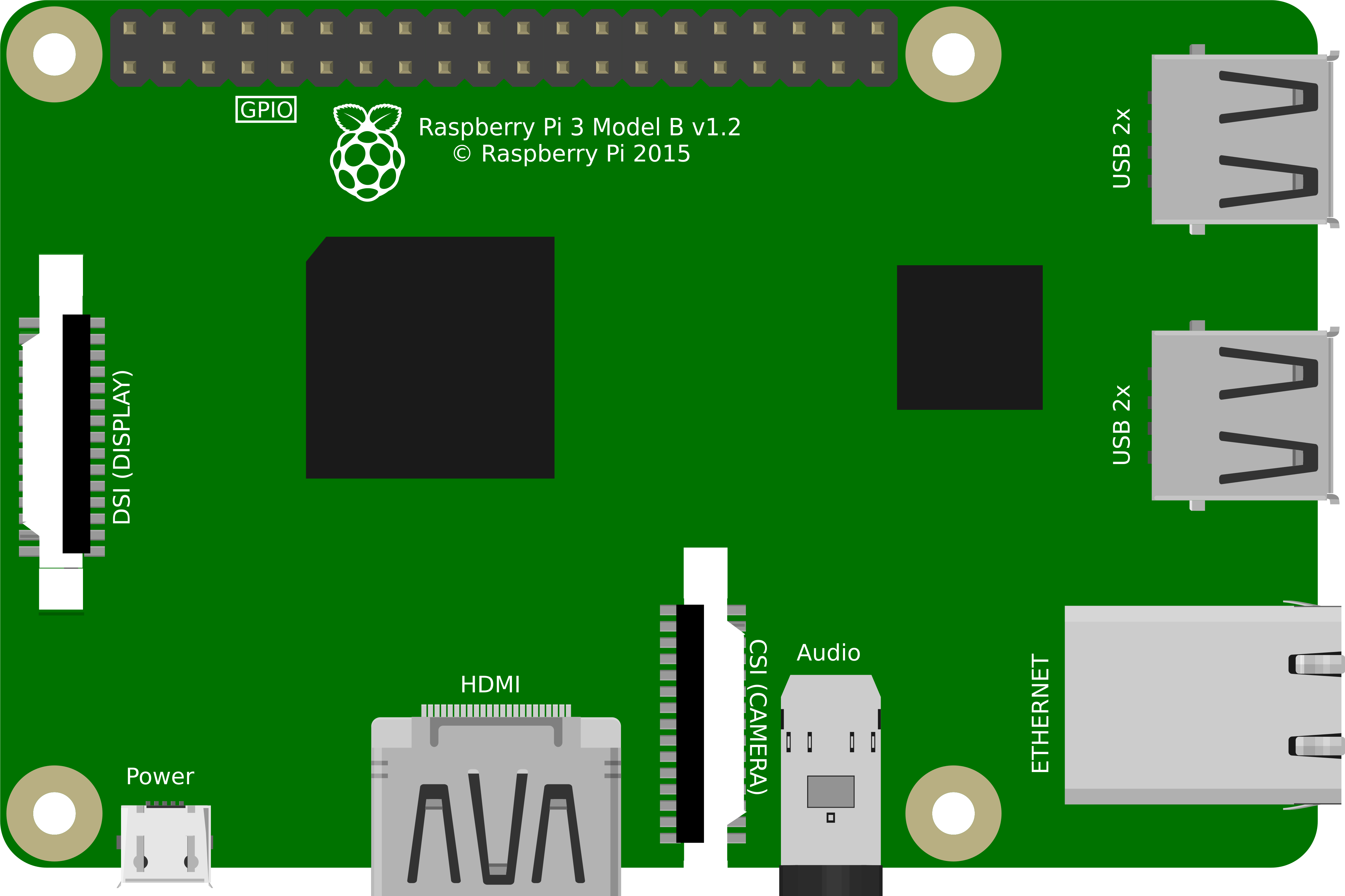
The Raspberry Pi 3B is a small, affordable computer designed for a variety of electronics projects and programming tasks. It features a quad-core ARM Cortex-A53 CPU, 1GB of RAM, and various connectivity options including HDMI, USB, and Ethernet. This versatile device is widely used in educational settings, DIY projects, and even in professional applications due to its powerful capabilities and ease of use.
Explore Projects Built with Raspberry Pi 3B
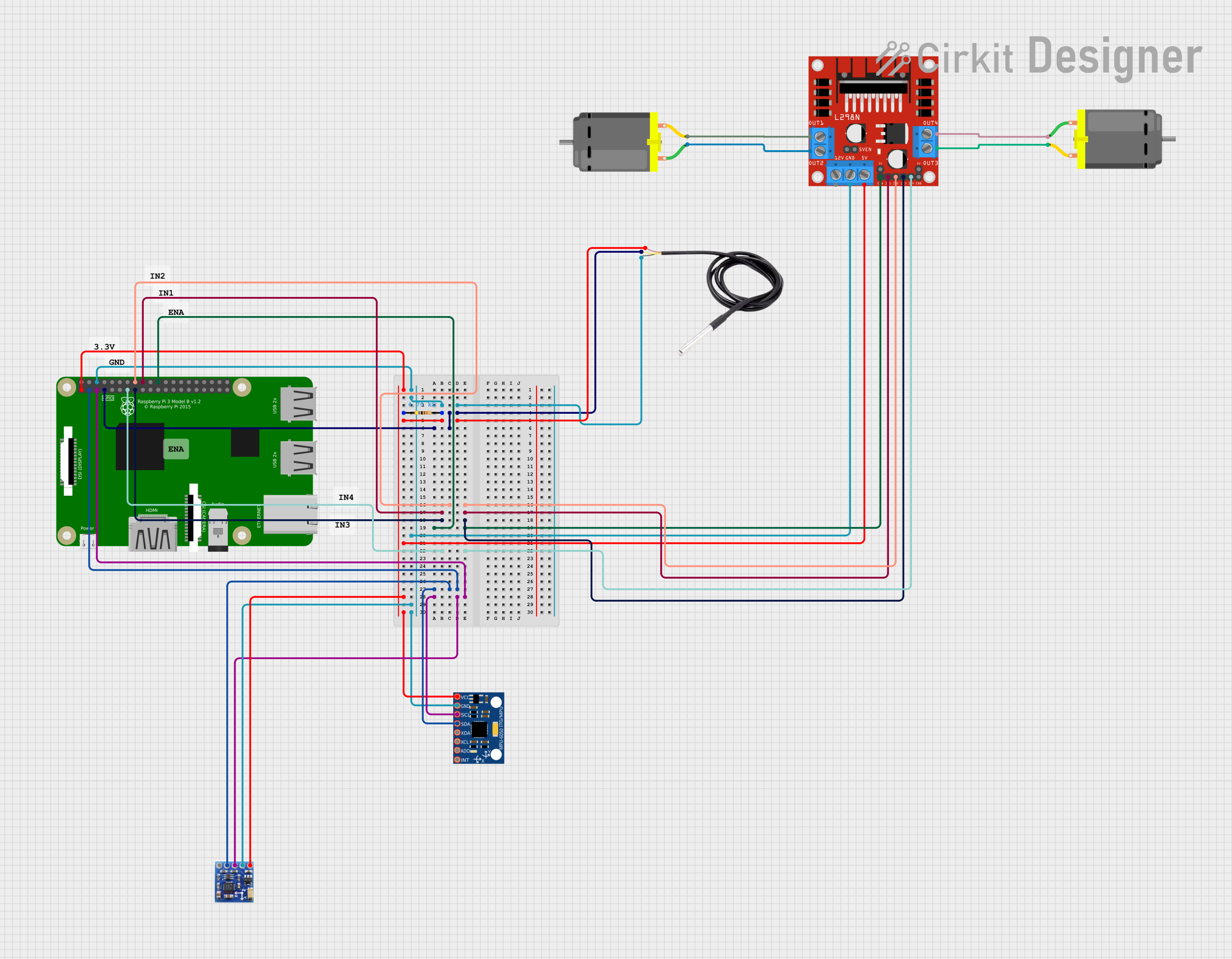
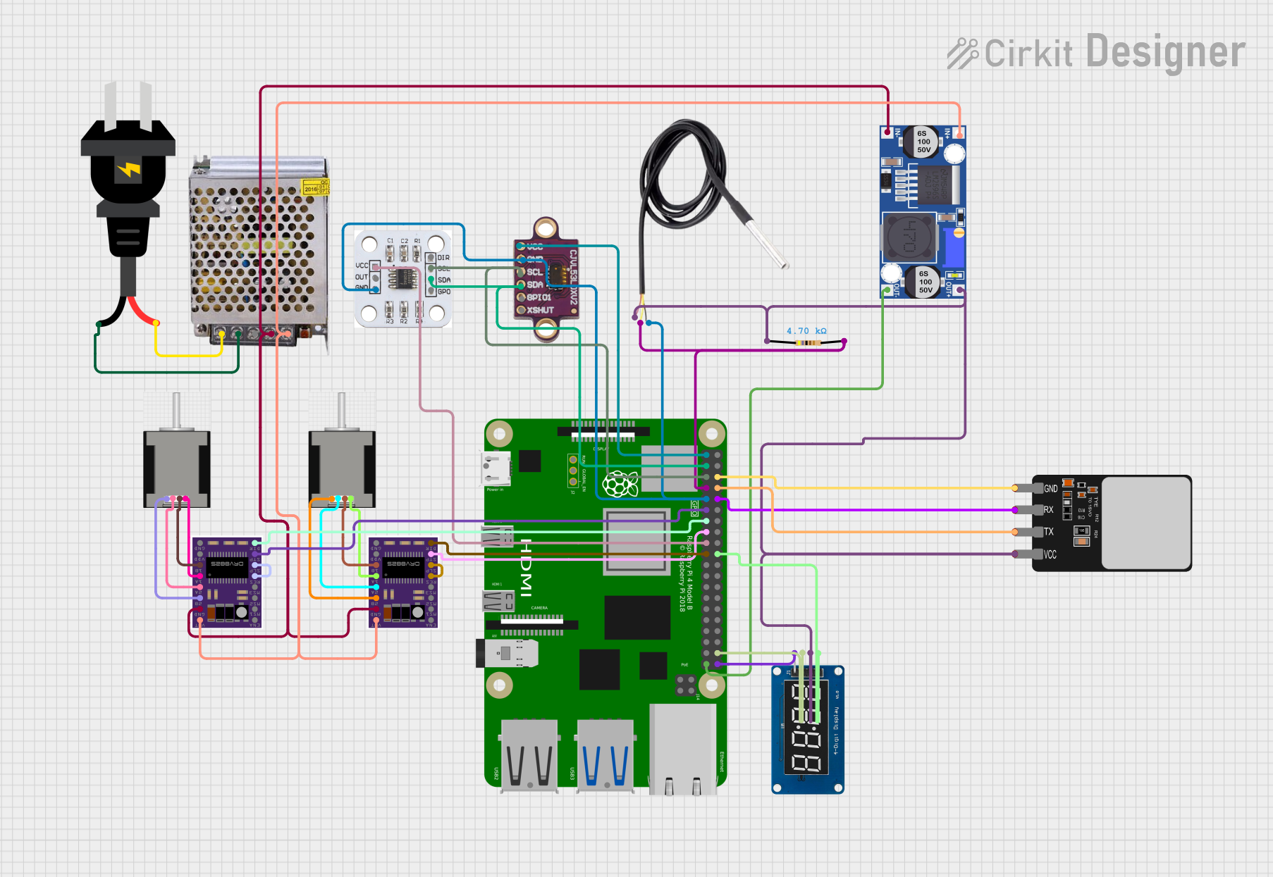
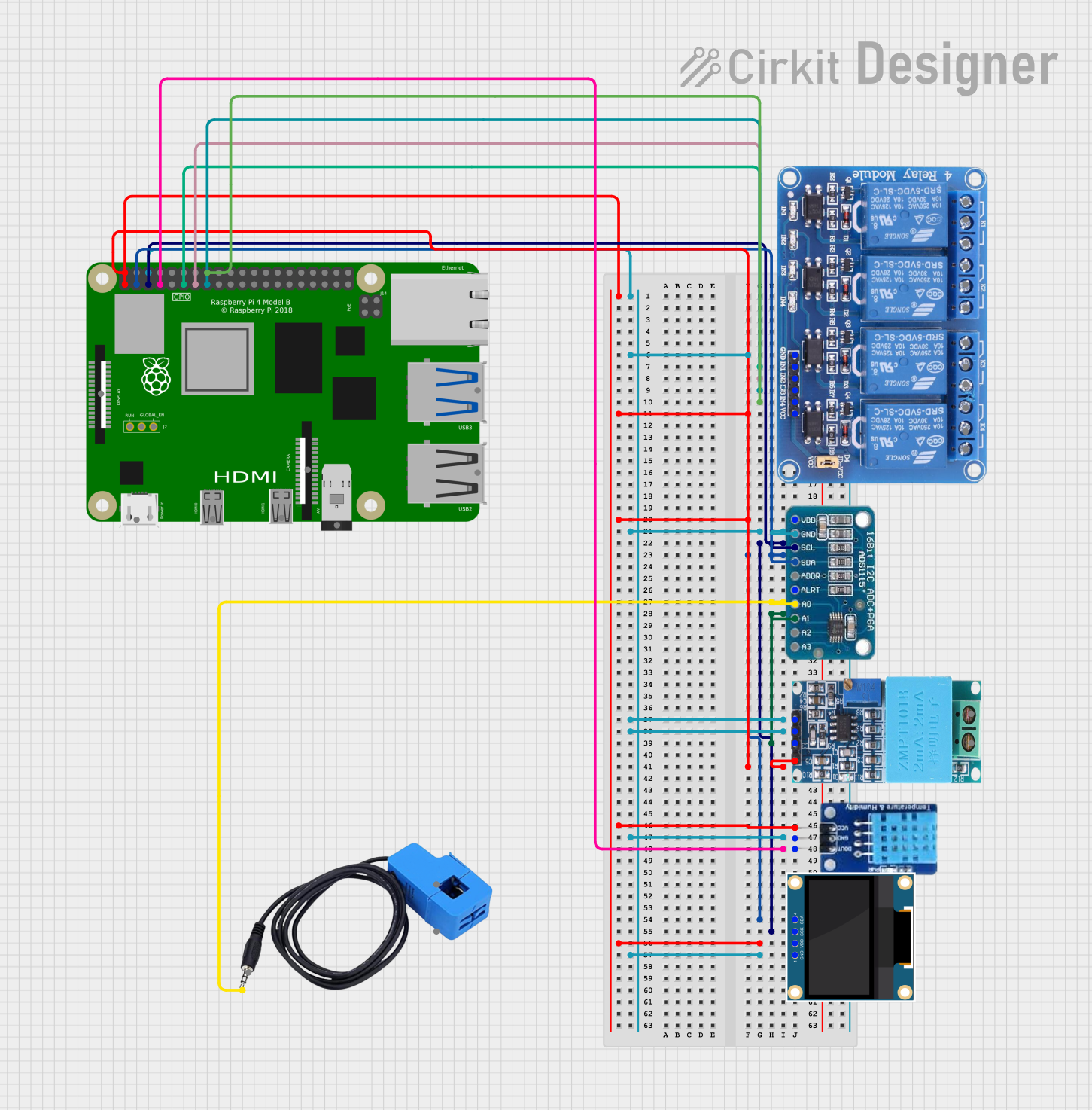
Explore Projects Built with Raspberry Pi 3B
Common Applications and Use Cases
- Educational Projects: Ideal for teaching programming and electronics.
- Home Automation: Can be used to control smart home devices.
- Media Centers: Perfect for setting up a home media center with software like Kodi.
- IoT Projects: Acts as a central hub for Internet of Things (IoT) devices.
- Retro Gaming: Can be used to emulate classic gaming consoles.
- Web Servers: Suitable for hosting small web servers and applications.
Technical Specifications
Key Technical Details
| Specification | Details |
|---|---|
| CPU | Quad-core ARM Cortex-A53 |
| RAM | 1GB LPDDR2 |
| GPU | Broadcom VideoCore IV |
| Connectivity | HDMI, 4x USB 2.0, Ethernet, Wi-Fi, Bluetooth |
| Storage | microSD |
| Power Supply | 5V/2.5A via micro USB |
| GPIO | 40-pin header |
| Operating System | Raspbian, Ubuntu, and other Linux distros |
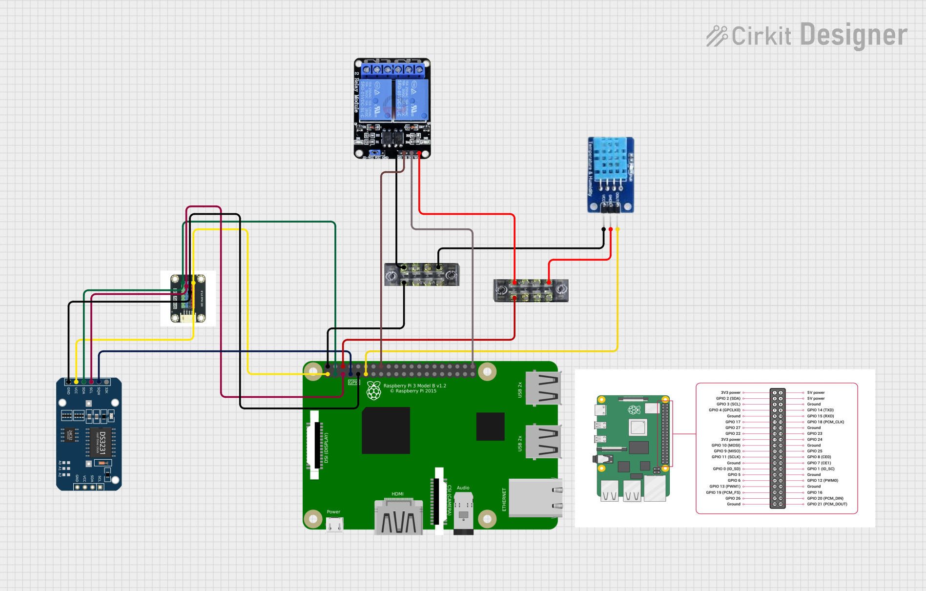
Pin Configuration and Descriptions
The Raspberry Pi 3B features a 40-pin GPIO header. Below is a table describing the pin configuration:
| Pin Number | Name | Description |
|---|---|---|
| 1 | 3.3V | Power (3.3V) |
| 2 | 5V | Power (5V) |
| 3 | GPIO 2 (SDA) | I2C Data |
| 4 | 5V | Power (5V) |
| 5 | GPIO 3 (SCL) | I2C Clock |
| 6 | GND | Ground |
| 7 | GPIO 4 | General Purpose I/O |
| 8 | GPIO 14 (TXD) | UART Transmit |
| 9 | GND | Ground |
| 10 | GPIO 15 (RXD) | UART Receive |
| ... | ... | ... |
| 39 | GND | Ground |
| 40 | GPIO 21 | General Purpose I/O |
Usage Instructions
How to Use the Raspberry Pi 3B in a Circuit
Powering the Raspberry Pi:
- Connect a 5V/2.5A power supply to the micro USB port.
- Ensure the power supply is stable to avoid damaging the board.
Connecting Peripherals:
- Connect a monitor via the HDMI port.
- Attach a keyboard and mouse to the USB ports.
- Insert a microSD card with a pre-installed operating system (e.g., Raspbian).
Networking:
- Connect an Ethernet cable for wired network access.
- Alternatively, configure Wi-Fi through the operating system.
Using GPIO Pins:
- Use jumper wires to connect sensors, LEDs, and other components to the GPIO pins.
- Ensure correct pin mapping to avoid short circuits.
Important Considerations and Best Practices
- Static Electricity: Handle the board with care to avoid static discharge.
- Cooling: Consider using a heat sink or fan for cooling during intensive tasks.
- Software Updates: Regularly update the operating system and software packages.
- Backup: Keep backups of important data on the microSD card.
Troubleshooting and FAQs
Common Issues Users Might Face
No Display Output:
- Solution: Check HDMI connections and ensure the monitor is set to the correct input source. Verify that the microSD card is properly inserted and contains a valid operating system.
Wi-Fi Connectivity Problems:
- Solution: Ensure the Wi-Fi credentials are correct. Reboot the router and the Raspberry Pi. Check for software updates that might fix connectivity issues.
Overheating:
- Solution: Use a heat sink or fan to cool the CPU. Ensure the Raspberry Pi is in a well-ventilated area.
Peripheral Devices Not Recognized:
- Solution: Check USB connections and try different ports. Ensure the devices are compatible with the Raspberry Pi.
Solutions and Tips for Troubleshooting
- Check Power Supply: Ensure the power supply provides a stable 5V/2.5A output.
- Re-flash the OS: If the system is unresponsive, re-flash the operating system on the microSD card.
- Use Diagnostic Tools: Utilize tools like
dmesgandlsusbto diagnose hardware issues.
Example Code for GPIO Control with Arduino UNO
If you are using the Raspberry Pi 3B in conjunction with an Arduino UNO, you can control the GPIO pins using the following Python code:
import RPi.GPIO as GPIO
import time
Set the GPIO mode
GPIO.setmode(GPIO.BCM)
Set up GPIO pin 18 as an output
GPIO.setup(18, GPIO.OUT)
Blink the LED connected to GPIO pin 18
try: while True: GPIO.output(18, GPIO.HIGH) # Turn on the LED time.sleep(1) # Wait for 1 second GPIO.output(18, GPIO.LOW) # Turn off the LED time.sleep(1) # Wait for 1 second except KeyboardInterrupt: pass
Clean up GPIO settings
GPIO.cleanup()
This code will blink an LED connected to GPIO pin 18 on the Raspberry Pi 3B. Make sure to connect a resistor in series with the LED to limit the current.
Conclusion
The Raspberry Pi 3B is a powerful and versatile tool for a wide range of applications. By following the usage instructions and best practices outlined in this documentation, you can effectively utilize this small computer for your projects. If you encounter any issues, refer to the troubleshooting section for solutions and tips. Happy tinkering!