How to Use KY-040: Examples, Pinouts, and Specs
Introduction
The KY-040 is a rotary encoder module designed for precise control of position and rotation. Unlike potentiometers, rotary encoders can rotate infinitely in either direction, making them ideal for applications requiring continuous or incremental adjustments. The module also includes a built-in push button, adding an extra layer of functionality for user input.
Explore Projects Built with KY-040


Explore Projects Built with KY-040
Common Applications and Use Cases
- Volume or menu control in audio and video devices
- Navigation in user interfaces (e.g., scrolling through menus)
- Robotics for position and speed control
- CNC machines and 3D printers for precise adjustments
- DIY electronics projects requiring rotary input
Technical Specifications
The KY-040 rotary encoder module has the following key specifications:
| Parameter | Value |
|---|---|
| Operating Voltage | 3.3V to 5V |
| Output Type | Digital (Incremental Encoder) |
| Number of Pins | 5 |
| Push Button | Integrated (Momentary Switch) |
| Rotational Steps | 20 steps per full rotation |
| Dimensions | 32mm x 19mm x 30mm (approximate) |
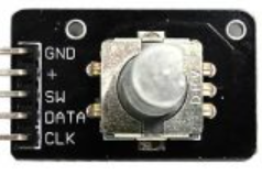
Pin Configuration and Descriptions
The KY-040 module has 5 pins, as described in the table below:
| Pin | Label | Description |
|---|---|---|
| 1 | GND | Ground connection for the module. |
| 2 | + | Power supply pin (3.3V to 5V). |
| 3 | SW | Push button output. Active LOW when the button is pressed. |
| 4 | DT | Data pin for the rotary encoder. Outputs pulses based on rotation direction. |
| 5 | CLK | Clock pin for the rotary encoder. Outputs pulses based on rotation movement. |
Usage Instructions
How to Use the KY-040 in a Circuit
Connect the Pins:
- Connect the
GNDpin to the ground of your circuit. - Connect the
+pin to a 3.3V or 5V power source. - Connect the
CLKandDTpins to digital input pins on your microcontroller. - Optionally, connect the
SWpin to another digital input pin to use the push button.
- Connect the
Read the Encoder Output:
- The
CLKandDTpins generate pulses as the encoder is rotated. The sequence of these pulses determines the direction of rotation (clockwise or counterclockwise). - The
SWpin outputs a LOW signal when the button is pressed.
- The
Debounce Signals:
- Rotary encoders and push buttons can produce noisy signals. Use software debouncing or external capacitors to ensure stable readings.
Important Considerations and Best Practices
- Power Supply: Ensure the module is powered within its operating voltage range (3.3V to 5V).
- Pull-Up Resistors: Use pull-up resistors on the
SW,CLK, andDTpins if your microcontroller does not have internal pull-ups enabled. - Signal Processing: Use interrupts or polling to read the encoder signals effectively, especially in time-sensitive applications.
- Mechanical Limitations: Avoid applying excessive force to the rotary shaft to prevent damage.
Example Code for Arduino UNO
Below is an example Arduino sketch to read the KY-040 rotary encoder and push button:
// Define pin connections for the KY-040 module
#define CLK 2  // Clock pin connected to digital pin 2
#define DT 3   // Data pin connected to digital pin 3
#define SW 4   // Switch pin connected to digital pin 4

int counter = 0;       // Variable to store the encoder position
int lastStateCLK;      // Previous state of the CLK pin
int currentStateCLK;   // Current state of the CLK pin
bool buttonPressed = false; // Flag for button press

void setup() {
  pinMode(CLK, INPUT);  // Set CLK pin as input
  pinMode(DT, INPUT);   // Set DT pin as input
  pinMode(SW, INPUT_PULLUP); // Set SW pin as input with pull-up resistor

  // Read the initial state of the CLK pin
  lastStateCLK = digitalRead(CLK);

  // Initialize serial communication for debugging
  Serial.begin(9600);
}

void loop() {
  // Read the current state of the CLK pin
  currentStateCLK = digitalRead(CLK);

  // Check if the state of CLK has changed
  if (currentStateCLK != lastStateCLK) {
    // Read the state of the DT pin
    int stateDT = digitalRead(DT);

    // Determine the rotation direction
    if (stateDT != currentStateCLK) {
      counter++; // Clockwise rotation
    } else {
      counter--; // Counterclockwise rotation
    }

    // Print the current counter value
    Serial.print("Position: ");
    Serial.println(counter);
  }

  // Update the last state of the CLK pin
  lastStateCLK = currentStateCLK;

  // Check if the button is pressed
  if (digitalRead(SW) == LOW) {
    if (!buttonPressed) {
      Serial.println("Button Pressed!");
      buttonPressed = true; // Set the flag to avoid multiple triggers
    }
  } else {
    buttonPressed = false; // Reset the flag when the button is released
  }
}
Troubleshooting and FAQs
Common Issues and Solutions
No Output from the Encoder:
- Ensure all connections are secure and correct.
- Verify that the module is powered within the specified voltage range.
- Check for loose or damaged wires.
Unstable or Erratic Readings:
- Add software debouncing to filter out noise from the encoder signals.
- Use external capacitors (e.g., 0.1µF) between the
CLK/DTpins and ground to reduce noise.
Push Button Not Responding:
- Verify that the
SWpin is connected to a digital input pin. - Ensure the microcontroller's internal pull-up resistor is enabled or use an external pull-up resistor.
- Verify that the
Incorrect Direction Detection:
- Swap the connections of the
CLKandDTpins to correct the direction.
- Swap the connections of the
FAQs
Q: Can the KY-040 be used with 3.3V microcontrollers like the ESP32?
A: Yes, the KY-040 is compatible with 3.3V systems. Ensure the power supply matches the microcontroller's voltage.
Q: How many steps does the encoder have per rotation?
A: The KY-040 typically has 20 steps per full rotation, but this may vary slightly depending on the module.
Q: Can I use the KY-040 for absolute position tracking?
A: No, the KY-040 is an incremental encoder and does not provide absolute position feedback. You must track the position in software.