Cirkit Designer Logo
Cirkit Designer
Your all-in-one circuit design IDE
Home / 
Component Documentation

How to Use XT60 Power Distribution Board: Examples, Pinouts, and Specs

Image of XT60 Power Distribution Board
Cirkit Designer LogoDesign with XT60 Power Distribution Board in Cirkit Designer

Introduction

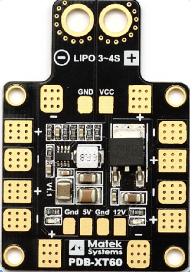
The XT60 Power Distribution Board (PDB-XT60) by Matek is a versatile and efficient device designed to distribute electrical power from a single source to multiple components in a circuit. This component is particularly popular in RC models and drones, where reliable and secure power distribution is crucial. The PDB-XT60 features XT60 connectors, ensuring a robust and efficient power transfer.

Explore Projects Built with XT60 Power Distribution Board

Use Cirkit Designer to design, explore, and prototype these projects online. Some projects support real-time simulation. Click "Open Project" to start designing instantly!
Battery-Powered Adjustable Voltage Regulator with Li-ion 18650 Batteries and BMS
Image of mini ups: A project utilizing XT60 Power Distribution Board in a practical application
This circuit is a power management system that uses four Li-ion 18650 batteries connected to a 2S 30A BMS for battery management and protection. The system includes step-up and step-down voltage regulators to provide adjustable output voltages, controlled by a rocker switch, and multiple DC jacks for power input and output.
Cirkit Designer LogoOpen Project in Cirkit Designer
Battery-Powered FPV Drone with Telemetry and Dual Motor Control
Image of Krul': A project utilizing XT60 Power Distribution Board in a practical application
This circuit appears to be a power distribution and control system for a vehicle with two motorized wheels, possibly a drone or a robot. It includes a lipo battery connected to a Power Distribution Board (PDB) that distributes power to two Electronic Speed Controllers (ESCs) which in turn control the speed and direction of the motors. The system also integrates a flight controller (H743-SLIM V3) for managing various peripherals including GPS, FPV camera system, and a telemetry link (ExpressLRS).
Cirkit Designer LogoOpen Project in Cirkit Designer
Battery-Powered 18650 Li-ion Charger with USB Output and Adjustable Voltage Regulator
Image of Breadboard: A project utilizing XT60 Power Distribution Board in a practical application
This circuit is a battery management and power supply system that uses three 3.7V batteries connected to a 3S 10A Li-ion 18650 Charger Protection Board Module for balanced charging and protection. The system includes a TP4056 Battery Charging Protection Module for additional charging safety, a Step Up Boost Power Converter to regulate and boost the voltage, and a USB regulator to provide a stable 5V output, controlled by a push switch.
Cirkit Designer LogoOpen Project in Cirkit Designer
Battery-Powered UPS with Step-Down Buck Converter and BMS
Image of Mini ups: A project utilizing XT60 Power Distribution Board in a practical application
This circuit is a power management system that steps down a 240V AC input to a lower DC voltage using a buck converter, which then powers a 40W UPS. The UPS is controlled by a rocker switch and is backed up by a battery management system (BMS) connected to three 3.7V batteries in series, ensuring continuous power supply.
Cirkit Designer LogoOpen Project in Cirkit Designer

Explore Projects Built with XT60 Power Distribution Board

Use Cirkit Designer to design, explore, and prototype these projects online. Some projects support real-time simulation. Click "Open Project" to start designing instantly!
Image of mini ups: A project utilizing XT60 Power Distribution Board in a practical application
Battery-Powered Adjustable Voltage Regulator with Li-ion 18650 Batteries and BMS
This circuit is a power management system that uses four Li-ion 18650 batteries connected to a 2S 30A BMS for battery management and protection. The system includes step-up and step-down voltage regulators to provide adjustable output voltages, controlled by a rocker switch, and multiple DC jacks for power input and output.
Cirkit Designer LogoOpen Project in Cirkit Designer
Image of Krul': A project utilizing XT60 Power Distribution Board in a practical application
Battery-Powered FPV Drone with Telemetry and Dual Motor Control
This circuit appears to be a power distribution and control system for a vehicle with two motorized wheels, possibly a drone or a robot. It includes a lipo battery connected to a Power Distribution Board (PDB) that distributes power to two Electronic Speed Controllers (ESCs) which in turn control the speed and direction of the motors. The system also integrates a flight controller (H743-SLIM V3) for managing various peripherals including GPS, FPV camera system, and a telemetry link (ExpressLRS).
Cirkit Designer LogoOpen Project in Cirkit Designer
Image of Breadboard: A project utilizing XT60 Power Distribution Board in a practical application
Battery-Powered 18650 Li-ion Charger with USB Output and Adjustable Voltage Regulator
This circuit is a battery management and power supply system that uses three 3.7V batteries connected to a 3S 10A Li-ion 18650 Charger Protection Board Module for balanced charging and protection. The system includes a TP4056 Battery Charging Protection Module for additional charging safety, a Step Up Boost Power Converter to regulate and boost the voltage, and a USB regulator to provide a stable 5V output, controlled by a push switch.
Cirkit Designer LogoOpen Project in Cirkit Designer
Image of Mini ups: A project utilizing XT60 Power Distribution Board in a practical application
Battery-Powered UPS with Step-Down Buck Converter and BMS
This circuit is a power management system that steps down a 240V AC input to a lower DC voltage using a buck converter, which then powers a 40W UPS. The UPS is controlled by a rocker switch and is backed up by a battery management system (BMS) connected to three 3.7V batteries in series, ensuring continuous power supply.
Cirkit Designer LogoOpen Project in Cirkit Designer

Technical Specifications

Key Technical Details

Parameter Specification
Manufacturer Matek
Part ID PDB-XT60
Input Voltage 3S-6S LiPo (11.1V - 22.2V)
Max Current 60A continuous, 120A peak
Output Voltage Same as input voltage
Dimensions 36mm x 50mm
Weight 10g
Connectors XT60 for input, solder pads for output

Pin Configuration and Descriptions

Pin/Pad Description
XT60 Input Connects to the power source (battery)
Solder Pads (1-6) Connects to various components (ESCs, etc.)
Ground Pads Common ground for all components

Usage Instructions

How to Use the Component in a Circuit

  1. Connect the Power Source:

    • Solder the XT60 connector to the input pads of the PDB-XT60. Ensure a secure and solid connection to handle high currents.
  2. Connect Components:

    • Solder the power leads of your components (e.g., ESCs, flight controllers) to the output solder pads on the PDB-XT60. Ensure correct polarity to avoid damage.
  3. Mounting:

    • Secure the PDB-XT60 in your RC model or drone using appropriate mounting hardware. Ensure it is placed in a location that minimizes vibration and physical stress.

Important Considerations and Best Practices

  • Heat Management:

    • Ensure adequate ventilation around the PDB-XT60 to prevent overheating, especially when operating at high currents.
  • Polarity Check:

    • Double-check the polarity of all connections before powering up to avoid damaging your components.
  • Soldering Quality:

    • Use high-quality solder and ensure all connections are solid and free of cold joints.
  • Insulation:

    • Insulate exposed solder joints to prevent short circuits.

Troubleshooting and FAQs

Common Issues Users Might Face

  1. No Power to Components:

    • Solution: Check all connections for continuity. Ensure the XT60 connector is securely connected to the power source.
  2. Overheating:

    • Solution: Ensure adequate ventilation and check for any short circuits. Verify that the current draw does not exceed the board's specifications.
  3. Intermittent Power Loss:

    • Solution: Inspect solder joints for cold joints or cracks. Re-solder if necessary.

FAQs

Q: Can I use the PDB-XT60 with a 4S LiPo battery? A: Yes, the PDB-XT60 supports 3S-6S LiPo batteries, including 4S (14.8V).

Q: How do I know if my connections are secure? A: Perform a continuity test with a multimeter to ensure all connections are solid. Visually inspect solder joints for any signs of poor connection.

Q: Can I connect more than six components to the PDB-XT60? A: The PDB-XT60 has six output pads. If you need to connect more components, consider using additional distribution boards or a custom wiring solution.

Example Code for Arduino UNO

While the PDB-XT60 itself does not directly interface with an Arduino UNO, it can be used to power components that do. Below is an example of how to power an Arduino UNO and a motor using the PDB-XT60.

/*
 * Example code to control a motor using Arduino UNO
 * powered by the PDB-XT60.
 */

const int motorPin = 9; // Pin connected to the motor driver

void setup() {
  pinMode(motorPin, OUTPUT); // Set motor pin as output
}

void loop() {
  digitalWrite(motorPin, HIGH); // Turn the motor on
  delay(1000); // Wait for 1 second
  digitalWrite(motorPin, LOW); // Turn the motor off
  delay(1000); // Wait for 1 second
}

In this setup, the PDB-XT60 distributes power from a LiPo battery to both the Arduino UNO and the motor. Ensure that the motor driver is properly connected to the PDB-XT60 and the Arduino UNO.

By following this documentation, users can effectively utilize the XT60 Power Distribution Board (PDB-XT60) in their projects, ensuring reliable and efficient power distribution.