Cirkit Designer Logo
Cirkit Designer
Your all-in-one circuit design IDE
Home / 
Component Documentation

How to Use MAX9814: Examples, Pinouts, and Specs

Image of MAX9814
Cirkit Designer LogoDesign with MAX9814 in Cirkit Designer

Introduction

The MAX9814 is a low-noise microphone amplifier with automatic gain control (AGC) designed for high-quality audio applications. It features a low-noise preamplifier, a variable gain amplifier, and an output buffer, making it ideal for use in microphones and audio recording devices. The AGC feature ensures consistent audio levels, making it particularly useful in environments with varying sound levels.

Explore Projects Built with MAX9814

Use Cirkit Designer to design, explore, and prototype these projects online. Some projects support real-time simulation. Click "Open Project" to start designing instantly!
ESP32-Based Multi-Sensor Health Monitoring System with Bluetooth Connectivity
Image of circuit diagram: A project utilizing MAX9814 in a practical application
This circuit features an ESP32-WROOM-32UE microcontroller as the central processing unit, interfacing with a variety of sensors and modules. It includes a MAX30100 pulse oximeter and heart-rate sensor, an MLX90614 infrared thermometer, an HC-05 Bluetooth module for wireless communication, and a Neo 6M GPS module for location tracking. All components are powered by a common voltage supply and are connected to specific GPIO pins on the ESP32 for data exchange, with the sensors using I2C communication and the modules using UART.
Cirkit Designer LogoOpen Project in Cirkit Designer
Battery-Powered Health Monitoring System with Nucleo WB55RG and OLED Display
Image of Pulsefex: A project utilizing MAX9814 in a practical application
This circuit is a multi-sensor data acquisition system that uses a Nucleo WB55RG microcontroller to interface with a digital temperature sensor (TMP102), a pulse oximeter and heart-rate sensor (MAX30102), and a 0.96" OLED display via I2C. Additionally, it includes a Sim800l module for GSM communication, powered by a 3.7V LiPo battery.
Cirkit Designer LogoOpen Project in Cirkit Designer
ESP32-Based Health Monitoring System with Bluetooth and GPS
Image of circuit diagram: A project utilizing MAX9814 in a practical application
This circuit integrates an ESP32 microcontroller with various sensors and modules, including a MAX30100 pulse oximeter, an MLX90614 infrared thermometer, a Neo 6M GPS module, and an HC-05 Bluetooth module. The ESP32 collects data from these sensors and modules via I2C and UART interfaces, enabling wireless communication and GPS tracking capabilities.
Cirkit Designer LogoOpen Project in Cirkit Designer
ESP32 and ESP32-CAM Based Wireless Temperature Monitoring System
Image of PLER: A project utilizing MAX9814 in a practical application
This circuit features an ESP32 microcontroller interfaced with an MLX90614 temperature sensor and an ESP32-CAM module for image capture. The power supply is managed by a 12V battery, a 7805 voltage regulator for 5V, and an AMS1117 regulator for 3.3V, ensuring stable operation of the components.
Cirkit Designer LogoOpen Project in Cirkit Designer

Explore Projects Built with MAX9814

Use Cirkit Designer to design, explore, and prototype these projects online. Some projects support real-time simulation. Click "Open Project" to start designing instantly!
Image of circuit diagram: A project utilizing MAX9814 in a practical application
ESP32-Based Multi-Sensor Health Monitoring System with Bluetooth Connectivity
This circuit features an ESP32-WROOM-32UE microcontroller as the central processing unit, interfacing with a variety of sensors and modules. It includes a MAX30100 pulse oximeter and heart-rate sensor, an MLX90614 infrared thermometer, an HC-05 Bluetooth module for wireless communication, and a Neo 6M GPS module for location tracking. All components are powered by a common voltage supply and are connected to specific GPIO pins on the ESP32 for data exchange, with the sensors using I2C communication and the modules using UART.
Cirkit Designer LogoOpen Project in Cirkit Designer
Image of Pulsefex: A project utilizing MAX9814 in a practical application
Battery-Powered Health Monitoring System with Nucleo WB55RG and OLED Display
This circuit is a multi-sensor data acquisition system that uses a Nucleo WB55RG microcontroller to interface with a digital temperature sensor (TMP102), a pulse oximeter and heart-rate sensor (MAX30102), and a 0.96" OLED display via I2C. Additionally, it includes a Sim800l module for GSM communication, powered by a 3.7V LiPo battery.
Cirkit Designer LogoOpen Project in Cirkit Designer
Image of circuit diagram: A project utilizing MAX9814 in a practical application
ESP32-Based Health Monitoring System with Bluetooth and GPS
This circuit integrates an ESP32 microcontroller with various sensors and modules, including a MAX30100 pulse oximeter, an MLX90614 infrared thermometer, a Neo 6M GPS module, and an HC-05 Bluetooth module. The ESP32 collects data from these sensors and modules via I2C and UART interfaces, enabling wireless communication and GPS tracking capabilities.
Cirkit Designer LogoOpen Project in Cirkit Designer
Image of PLER: A project utilizing MAX9814 in a practical application
ESP32 and ESP32-CAM Based Wireless Temperature Monitoring System
This circuit features an ESP32 microcontroller interfaced with an MLX90614 temperature sensor and an ESP32-CAM module for image capture. The power supply is managed by a 12V battery, a 7805 voltage regulator for 5V, and an AMS1117 regulator for 3.3V, ensuring stable operation of the components.
Cirkit Designer LogoOpen Project in Cirkit Designer

Common Applications and Use Cases

  • Microphone preamplifiers
  • Audio recording devices
  • Voice recognition systems
  • Hearing aids
  • Telecommunication devices

Technical Specifications

Key Technical Details

Parameter Value
Supply Voltage 2.7V to 5.5V
Quiescent Current 3mA (typical)
Gain 40dB (fixed)
AGC Range 20dB
Output Impedance 200Ω
Noise Figure 4.5dB
THD+N 0.04% (typical)
Operating Temperature Range -40°C to +85°C

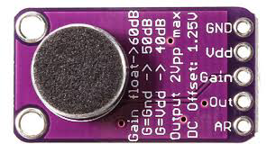
Pin Configuration and Descriptions

Pin Number Pin Name Description
1 GND Ground
2 VDD Power Supply (2.7V to 5.5V)
3 OUT Output Signal
4 IN+ Non-inverting Input
5 IN- Inverting Input
6 BYPASS Bypass Capacitor Connection for Noise Reduction
7 TH AGC Threshold Adjustment
8 AR AGC Attack/Release Time Adjustment

Usage Instructions

How to Use the MAX9814 in a Circuit

  1. Power Supply: Connect the VDD pin to a stable power supply within the range of 2.7V to 5.5V. Connect the GND pin to the ground of the circuit.
  2. Input Connections: Connect the microphone or audio signal source to the IN+ and IN- pins. The IN+ pin is the non-inverting input, and the IN- pin is the inverting input.
  3. Output Connection: Connect the OUT pin to the next stage of your audio processing circuit, such as an ADC or another amplifier.
  4. Bypass Capacitor: Connect a capacitor (typically 0.1µF) between the BYPASS pin and GND to reduce noise.
  5. AGC Threshold and Timing: Adjust the AGC threshold and attack/release times by connecting appropriate resistors or capacitors to the TH and AR pins.

Important Considerations and Best Practices

  • Power Supply Decoupling: Use a decoupling capacitor (e.g., 0.1µF) close to the VDD pin to filter out noise from the power supply.
  • PCB Layout: Keep the traces for the input signals (IN+ and IN-) as short as possible to minimize noise pickup.
  • AGC Settings: Fine-tune the AGC settings based on your specific application requirements to achieve the desired audio performance.

Example Circuit with Arduino UNO

/*
 * Example code to interface MAX9814 with Arduino UNO.
 * This code reads the analog output from the MAX9814 and prints the
 * value to the Serial Monitor.
 */

const int micPin = A0; // MAX9814 OUT pin connected to Arduino A0

void setup() {
  Serial.begin(9600); // Initialize serial communication at 9600 baud
}

void loop() {
  int micValue = analogRead(micPin); // Read the analog value from the mic
  Serial.println(micValue); // Print the value to the Serial Monitor
  delay(100); // Delay for 100ms
}

Troubleshooting and FAQs

Common Issues and Solutions

  1. No Output Signal

    • Check Power Supply: Ensure that the VDD pin is connected to a stable power supply within the specified range.
    • Verify Connections: Double-check all connections, especially the input and output pins.
  2. High Noise Levels

    • Bypass Capacitor: Ensure that a capacitor is connected between the BYPASS pin and GND.
    • PCB Layout: Minimize the length of input signal traces and keep them away from noisy components.
  3. AGC Not Functioning Properly

    • Threshold and Timing Components: Verify that the resistors and capacitors connected to the TH and AR pins are within the recommended values.

FAQs

Q: Can I use the MAX9814 with a 3.3V power supply? A: Yes, the MAX9814 operates within a supply voltage range of 2.7V to 5.5V, so a 3.3V power supply is suitable.

Q: How do I adjust the gain of the MAX9814? A: The MAX9814 has a fixed gain of 40dB. However, you can adjust the AGC threshold and attack/release times to control the overall audio level.

Q: What type of microphone is compatible with the MAX9814? A: The MAX9814 is compatible with both electret and MEMS microphones.

By following this documentation, users can effectively integrate the MAX9814 into their audio applications, ensuring high-quality audio performance with minimal noise and consistent levels.