
How to Use BMS: Examples, Pinouts, and Specs
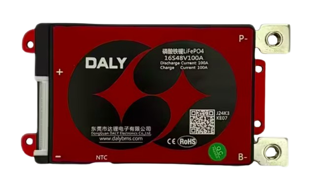
 Design with BMS in Cirkit Designer
Introduction
A Battery Management System (BMS) is an electronic system designed to monitor and manage rechargeable batteries. It ensures the safe operation of the battery by monitoring its state, calculating secondary data (such as charge and discharge rates), and controlling its environment. The BMS plays a critical role in optimizing battery performance, extending its lifespan, and preventing hazardous conditions such as overcharging, over-discharging, or overheating.
Explore Projects Built with BMS
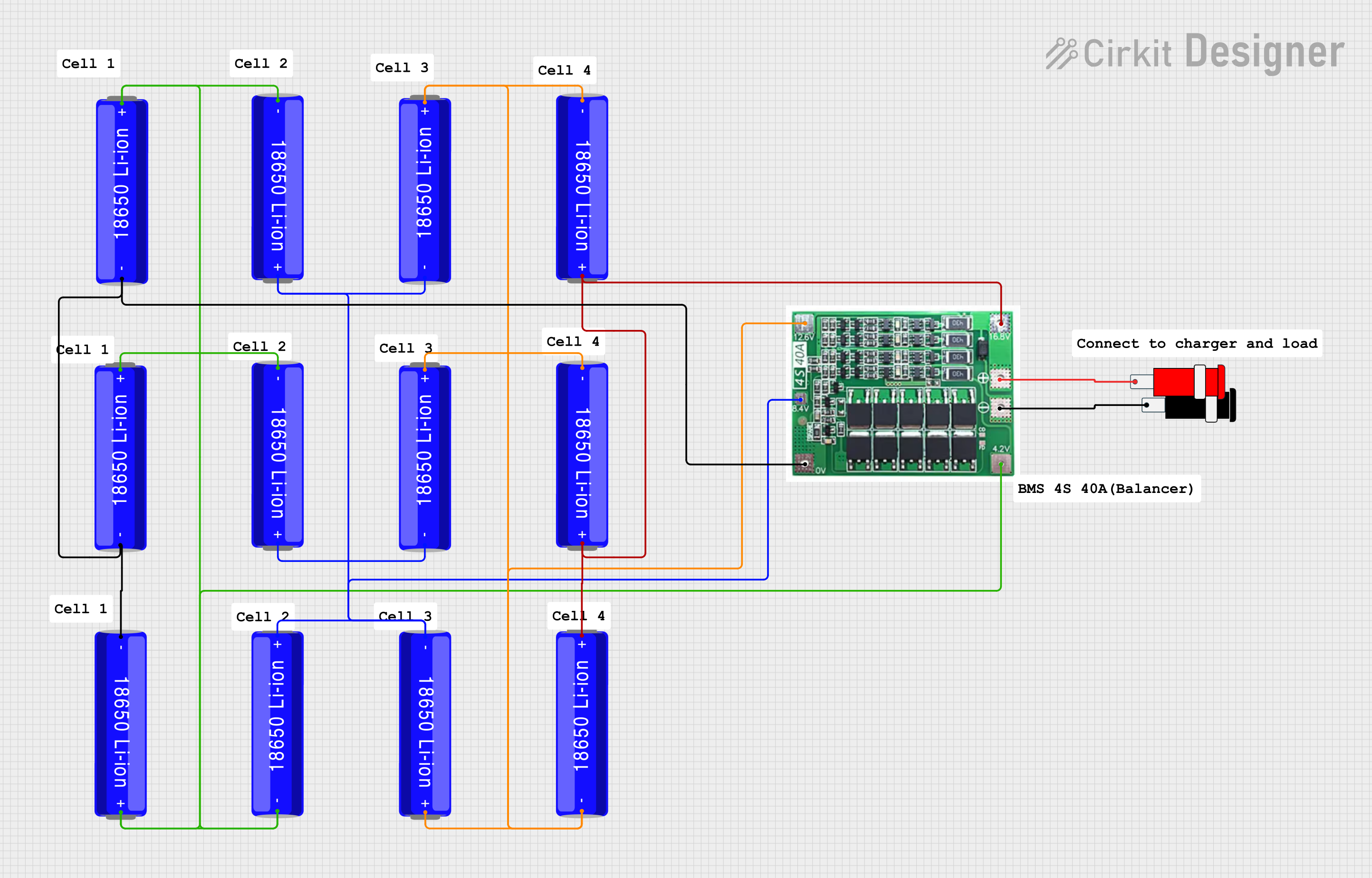 Open Project in Cirkit Designer
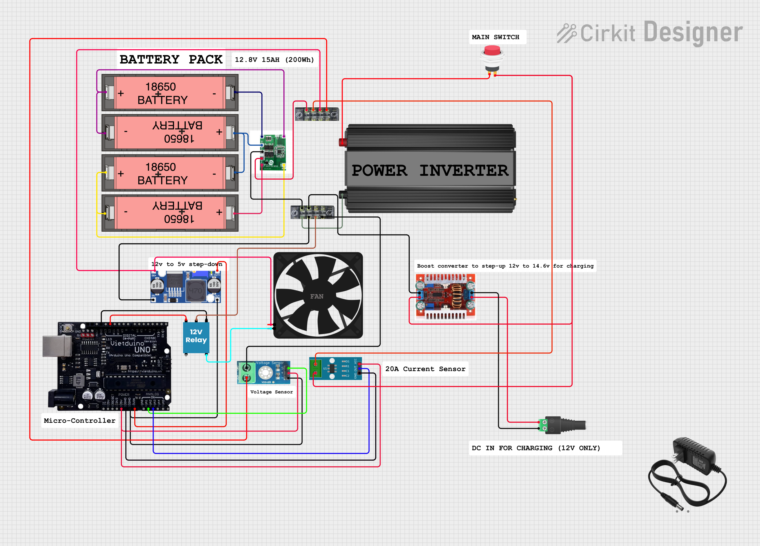 Open Project in Cirkit Designer
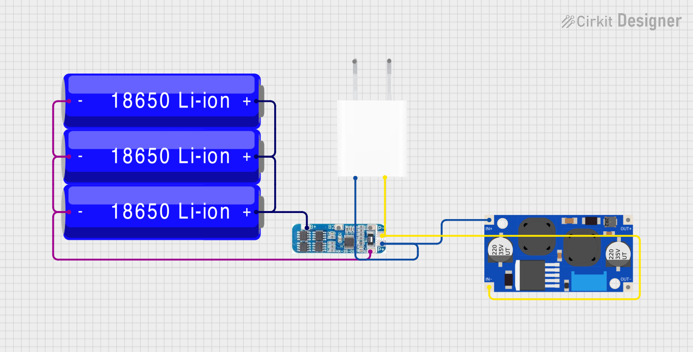 Open Project in Cirkit Designer
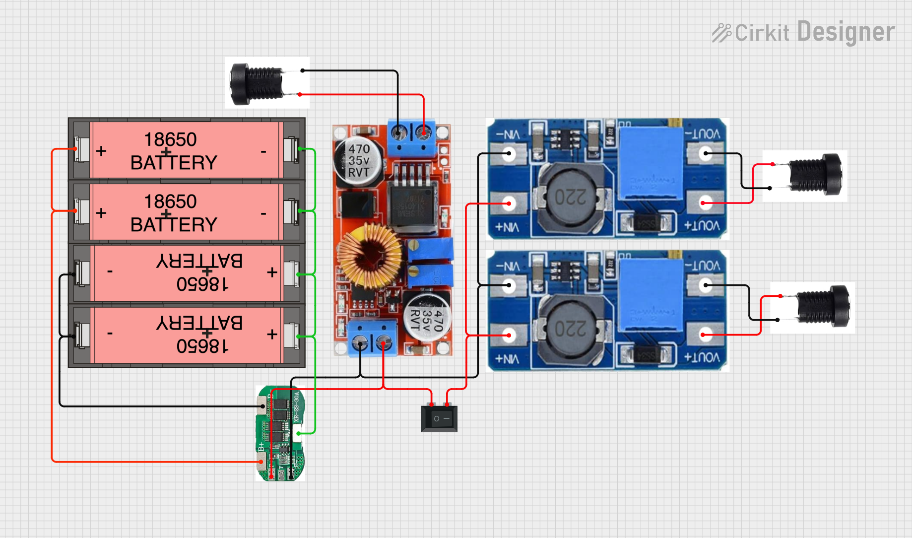 Open Project in Cirkit Designer
Explore Projects Built with BMS
Open Project in Cirkit DesignerOpen Project in Cirkit DesignerOpen Project in Cirkit DesignerOpen Project in Cirkit DesignerCommon Applications and Use Cases
- Electric vehicles (EVs) and hybrid electric vehicles (HEVs)
- Renewable energy storage systems (e.g., solar and wind energy)
- Consumer electronics (e.g., laptops, smartphones, and power banks)
- Uninterruptible Power Supplies (UPS)
- Industrial and medical equipment requiring reliable battery operation
Technical Specifications
Key Technical Details
| Parameter | Description |
|---|---|
| Input Voltage Range | Typically 3.7V to 48V (varies based on battery type and application) |
| Supported Battery Types | Lithium-ion (Li-ion), Lithium Polymer (LiPo), Lead-acid, Nickel-based cells |
| Overcharge Protection | Prevents charging beyond a specified voltage threshold |
| Over-discharge Protection | Prevents discharging below a specified voltage threshold |
| Balancing Current | Typically 50mA to 200mA (for cell balancing in multi-cell systems) |
| Operating Temperature Range | -20°C to 60°C |
| Communication Protocols | I2C, SPI, UART (varies by model) |
Pin Configuration and Descriptions
| Pin Name | Description |
|---|---|
| B+ | Battery positive terminal |
| B- | Battery negative terminal |
| P+ | Positive terminal for load/charger |
| P- | Negative terminal for load/charger |
| C+ | Charger positive terminal (if separate from P+) |
| C- | Charger negative terminal (if separate from P-) |
| Balance Pins | Pins connected to individual battery cells for voltage monitoring and balancing |
Usage Instructions
How to Use the BMS in a Circuit
Connect the Battery Pack:
- Connect the positive terminal of the battery pack to the
B+pin. - Connect the negative terminal of the battery pack to the
B-pin. - For multi-cell systems, connect the balance wires from each cell to the corresponding balance pins.
- Connect the positive terminal of the battery pack to the
Connect the Load and Charger:
- Connect the load's positive terminal to the
P+pin and the negative terminal to theP-pin. - If the charger has separate terminals, connect them to the
C+andC-pins.
- Connect the load's positive terminal to the
Power On:
- Ensure all connections are secure and within the BMS's voltage and current ratings.
- Power on the system and monitor the BMS's status indicators (if available).
Monitor and Configure:
- Use the communication interface (e.g., I2C, SPI, or UART) to monitor battery parameters such as voltage, current, and temperature.
- Configure protection thresholds (if supported) using the manufacturer's software or firmware.
Important Considerations and Best Practices
- Battery Compatibility: Ensure the BMS is compatible with the type and configuration of your battery pack.
- Cell Balancing: For multi-cell systems, verify that the BMS supports cell balancing to maintain uniform voltage across cells.
- Heat Dissipation: Avoid overheating by ensuring proper ventilation or using a heatsink if necessary.
- Wiring: Use appropriately rated wires and connectors to handle the current and voltage of your system.
- Firmware Updates: If the BMS supports firmware updates, keep it updated to benefit from the latest features and bug fixes.
Example: Using a BMS with an Arduino UNO
Below is an example of how to monitor battery voltage using a BMS with an I2C interface:
#include <Wire.h>

// Define the I2C address of the BMS (replace with your BMS's address)
#define BMS_I2C_ADDRESS 0x36

void setup() {
  Wire.begin(); // Initialize I2C communication
  Serial.begin(9600); // Initialize serial communication for debugging
}

void loop() {
  Wire.beginTransmission(BMS_I2C_ADDRESS); // Start communication with BMS
  Wire.write(0x02); // Request voltage data (register address may vary)
  Wire.endTransmission(false); // End transmission without releasing the bus

  Wire.requestFrom(BMS_I2C_ADDRESS, 2); // Request 2 bytes of data
  if (Wire.available() == 2) {
    uint16_t voltage = Wire.read() << 8 | Wire.read(); // Combine two bytes
    Serial.print("Battery Voltage: ");
    Serial.print(voltage / 1000.0); // Convert to volts (example scaling)
    Serial.println(" V");
  }

  delay(1000); // Wait 1 second before the next reading
}
Troubleshooting and FAQs
Common Issues and Solutions
BMS Not Powering On:
- Cause: Incorrect wiring or insufficient input voltage.
- Solution: Double-check all connections and ensure the battery voltage is within the BMS's input range.
Overheating:
- Cause: Excessive current draw or poor ventilation.
- Solution: Reduce the load current or improve heat dissipation with a heatsink or fan.
Uneven Cell Voltages:
- Cause: Cell imbalance in multi-cell systems.
- Solution: Use a BMS with active or passive cell balancing features.
Communication Failure:
- Cause: Incorrect I2C/SPI wiring or address mismatch.
- Solution: Verify the communication protocol, wiring, and BMS address.
FAQs
Can I use a BMS with a different battery chemistry?
- Only if the BMS explicitly supports that chemistry. Using an incompatible BMS can damage the battery or the system.
What happens if I exceed the BMS's current rating?
- The BMS will typically shut down to protect the battery and itself. Prolonged overcurrent conditions can damage the BMS.
Do I need a separate charger with a BMS?
- Yes, the BMS manages the battery but does not replace the need for a compatible charger.
How do I know if my BMS is working correctly?
- Monitor the battery parameters (voltage, current, temperature) and ensure they remain within safe limits. Check for any error indicators on the BMS.