Cirkit Designer Logo
Cirkit Designer
Your all-in-one circuit design IDE
Home / 
Component Documentation

How to Use DIODE-ZENER: Examples, Pinouts, and Specs


Image of DIODE-ZENER
Cirkit Designer LogoDesign with DIODE-ZENER in Cirkit Designer

Introduction

A Zener diode is a type of semiconductor device that allows current to flow in the reverse direction when a specific reverse voltage, known as the Zener voltage, is reached. Unlike regular diodes, which block reverse current, Zener diodes are designed to operate in the breakdown region without damage. This unique property makes them ideal for voltage regulation and protection in electronic circuits.

Explore Projects Built with DIODE-ZENER
Use Cirkit Designer to design, explore, and prototype these projects online. Some projects support real-time simulation. Click "Open Project" to start designing instantly!
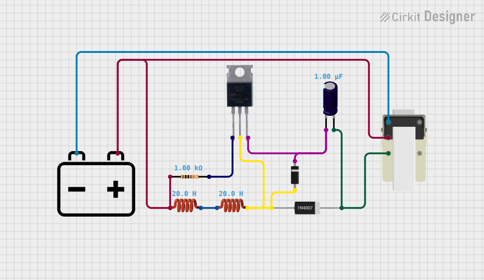
Voltage Regulated Transformer Power Supply Circuit
Image of revisi 3 : A project utilizing DIODE-ZENER in a practical application
This circuit appears to be a power supply circuit with a transformer connected to a 12V battery for voltage step-up or step-down. It includes a rectification stage with a 1N4007 diode, smoothing with an electrolytic capacitor, and regulation using a Zener diode. Additionally, there are inductors for filtering and a BT139 600 triac for controlling AC power, possibly for dimming or switching applications.
Cirkit Designer LogoOpen Project in Cirkit Designer
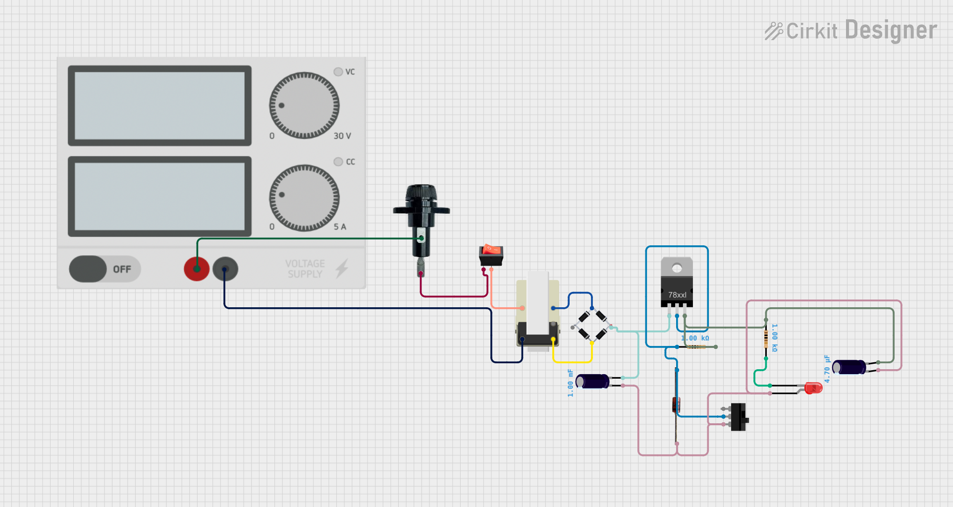
AC to DC Power Supply with Voltage Regulation and Overcurrent Protection
Image of PENGATUR VOLTAN: A project utilizing DIODE-ZENER in a practical application
This circuit appears to be a power supply unit with a transformer for stepping down voltage, a bridge rectifier for converting AC to DC, and a voltage regulator for stabilizing the output voltage. It includes a Zener diode for overvoltage protection, capacitors for smoothing out ripples in the DC supply, and a fuse for overcurrent protection. A toggle switch and a rocker switch are used to control the power flow, and there is an LED indicator connected through resistors, likely for power-on indication.
Cirkit Designer LogoOpen Project in Cirkit Designer
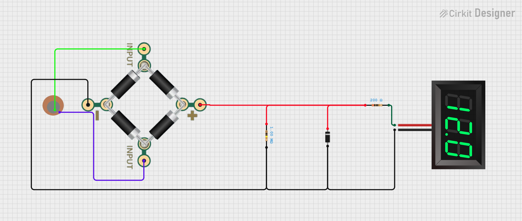
Piezo Sensor-Based Voltage Measurement Circuit with 7-Segment Display
Image of piezoelectric wiring: A project utilizing DIODE-ZENER in a practical application
This circuit converts the AC signal from a piezo sensor into a DC voltage using a bridge rectifier and stabilizes it with a Zener diode. The resulting voltage is then displayed on a 7-segment panel voltmeter, with resistors used for current limiting and voltage division.
Cirkit Designer LogoOpen Project in Cirkit Designer
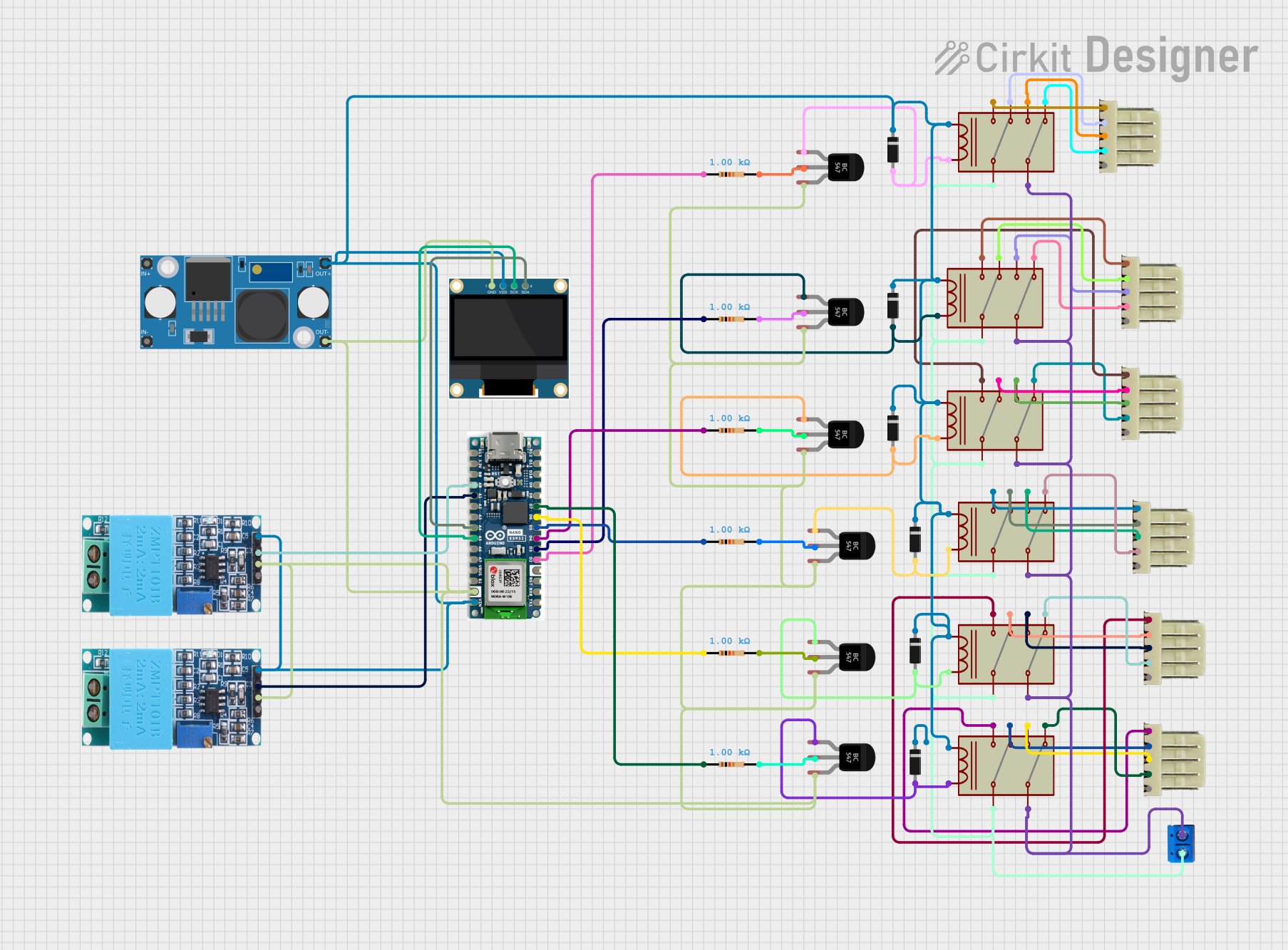
ESP32-Based Smart Voltage Monitoring and Relay Control System with Solar Integration
Image of ATS (Automatic Transfer Switch): A project utilizing DIODE-ZENER in a practical application
This circuit is designed to monitor and control power distribution using an Arduino Nano ESP32 microcontroller, which interfaces with voltage sensors (ZMPT101B modules) and an OLED display for real-time monitoring. It uses multiple relays driven by BC547 transistors to switch between power sources (solar and WAPDA) based on voltage thresholds, ensuring safe operating conditions. The system's functionality includes voltage safety checks, solar power detection, and automatic relay control, with the ability to display status messages on the OLED.
Cirkit Designer LogoOpen Project in Cirkit Designer

Explore Projects Built with DIODE-ZENER

Use Cirkit Designer to design, explore, and prototype these projects online. Some projects support real-time simulation. Click "Open Project" to start designing instantly!
Image of revisi 3 : A project utilizing DIODE-ZENER in a practical application
Voltage Regulated Transformer Power Supply Circuit
This circuit appears to be a power supply circuit with a transformer connected to a 12V battery for voltage step-up or step-down. It includes a rectification stage with a 1N4007 diode, smoothing with an electrolytic capacitor, and regulation using a Zener diode. Additionally, there are inductors for filtering and a BT139 600 triac for controlling AC power, possibly for dimming or switching applications.
Cirkit Designer LogoOpen Project in Cirkit Designer
Image of PENGATUR VOLTAN: A project utilizing DIODE-ZENER in a practical application
AC to DC Power Supply with Voltage Regulation and Overcurrent Protection
This circuit appears to be a power supply unit with a transformer for stepping down voltage, a bridge rectifier for converting AC to DC, and a voltage regulator for stabilizing the output voltage. It includes a Zener diode for overvoltage protection, capacitors for smoothing out ripples in the DC supply, and a fuse for overcurrent protection. A toggle switch and a rocker switch are used to control the power flow, and there is an LED indicator connected through resistors, likely for power-on indication.
Cirkit Designer LogoOpen Project in Cirkit Designer
Image of piezoelectric wiring: A project utilizing DIODE-ZENER in a practical application
Piezo Sensor-Based Voltage Measurement Circuit with 7-Segment Display
This circuit converts the AC signal from a piezo sensor into a DC voltage using a bridge rectifier and stabilizes it with a Zener diode. The resulting voltage is then displayed on a 7-segment panel voltmeter, with resistors used for current limiting and voltage division.
Cirkit Designer LogoOpen Project in Cirkit Designer
Image of ATS (Automatic Transfer Switch): A project utilizing DIODE-ZENER in a practical application
ESP32-Based Smart Voltage Monitoring and Relay Control System with Solar Integration
This circuit is designed to monitor and control power distribution using an Arduino Nano ESP32 microcontroller, which interfaces with voltage sensors (ZMPT101B modules) and an OLED display for real-time monitoring. It uses multiple relays driven by BC547 transistors to switch between power sources (solar and WAPDA) based on voltage thresholds, ensuring safe operating conditions. The system's functionality includes voltage safety checks, solar power detection, and automatic relay control, with the ability to display status messages on the OLED.
Cirkit Designer LogoOpen Project in Cirkit Designer

Common Applications and Use Cases

  • Voltage regulation in power supplies
  • Overvoltage protection for sensitive components
  • Reference voltage generation in precision circuits
  • Waveform clipping and shaping in signal processing

Technical Specifications

Below are the general technical specifications for a Zener diode. Note that specific values depend on the model and manufacturer.

Key Technical Details

  • Zener Voltage (Vz): Typically ranges from 2.4V to 200V
  • Power Dissipation (Pz): Commonly 0.25W, 0.5W, 1W, or higher
  • Maximum Reverse Current (Ir): Typically in the microampere range
  • Temperature Coefficient: Varies with Zener voltage, typically ±0.05%/°C
  • Forward Voltage (Vf): Approximately 0.7V (similar to standard diodes)
  • Operating Temperature Range: -65°C to +150°C

Pin Configuration and Descriptions

Zener diodes are two-terminal devices with the following pin configuration:

Pin Name Description
Anode Positive terminal of the diode
Cathode Negative terminal, marked with a band

The cathode is the terminal where reverse current flows when the Zener voltage is reached.

Usage Instructions

How to Use the Component in a Circuit

  1. Voltage Regulation:

    • Connect the Zener diode in reverse bias (cathode to positive voltage, anode to ground).
    • Place a current-limiting resistor in series with the diode to prevent excessive current.
    • The Zener diode will maintain a stable voltage across its terminals equal to its Zener voltage.
  2. Overvoltage Protection:

    • Place the Zener diode across the load in reverse bias.
    • When the input voltage exceeds the Zener voltage, the diode conducts and clamps the voltage to a safe level.
  3. Reference Voltage:

    • Use the Zener diode in reverse bias to provide a stable reference voltage for other circuit components.

Important Considerations and Best Practices

  • Always use a current-limiting resistor to avoid exceeding the diode's maximum power dissipation.
  • Choose a Zener diode with a Zener voltage close to the desired regulated voltage.
  • Ensure the diode's power rating is sufficient for the application.
  • Avoid operating the diode at temperatures beyond its specified range.

Example: Using a Zener Diode with Arduino UNO

Below is an example of using a Zener diode for voltage regulation in a circuit connected to an Arduino UNO.

Circuit Description

  • A 5.1V Zener diode is used to regulate the voltage supplied to an analog input pin of the Arduino.
  • The Zener diode ensures that the voltage does not exceed 5.1V, protecting the Arduino from overvoltage.

Code Example

// Arduino code to read a voltage regulated by a Zener diode
const int analogPin = A0; // Analog pin connected to the Zener diode
float voltage = 0.0;      // Variable to store the measured voltage

void setup() {
  Serial.begin(9600); // Initialize serial communication
}

void loop() {
  int sensorValue = analogRead(analogPin); // Read the analog input
  voltage = sensorValue * (5.0 / 1023.0);  // Convert to voltage
  Serial.print("Voltage: ");
  Serial.print(voltage);
  Serial.println(" V");
  delay(1000); // Wait for 1 second before the next reading
}

Troubleshooting and FAQs

Common Issues Users Might Face

  1. Zener Diode Overheating:

    • Cause: Excessive current through the diode.
    • Solution: Use a higher-value current-limiting resistor or a diode with a higher power rating.
  2. Voltage Not Regulated Properly:

    • Cause: Incorrect Zener voltage or insufficient input voltage.
    • Solution: Verify the Zener voltage and ensure the input voltage is at least 1V higher than the Zener voltage.
  3. No Voltage Across the Diode:

    • Cause: Incorrect polarity or open circuit.
    • Solution: Check the diode's orientation and ensure proper connections.

Solutions and Tips for Troubleshooting

  • Use a multimeter to verify the Zener voltage and check for proper operation.
  • Ensure the current-limiting resistor is correctly calculated using the formula: [ R = \frac{V_{in} - V_z}{I_z} ] where ( V_{in} ) is the input voltage, ( V_z ) is the Zener voltage, and ( I_z ) is the desired current through the diode.
  • If the diode fails repeatedly, consider using a diode with a higher power rating or improving heat dissipation.

By following these guidelines, you can effectively use a Zener diode in your electronic projects.