How to Use PLC PANASONIC: Examples, Pinouts, and Specs
Introduction
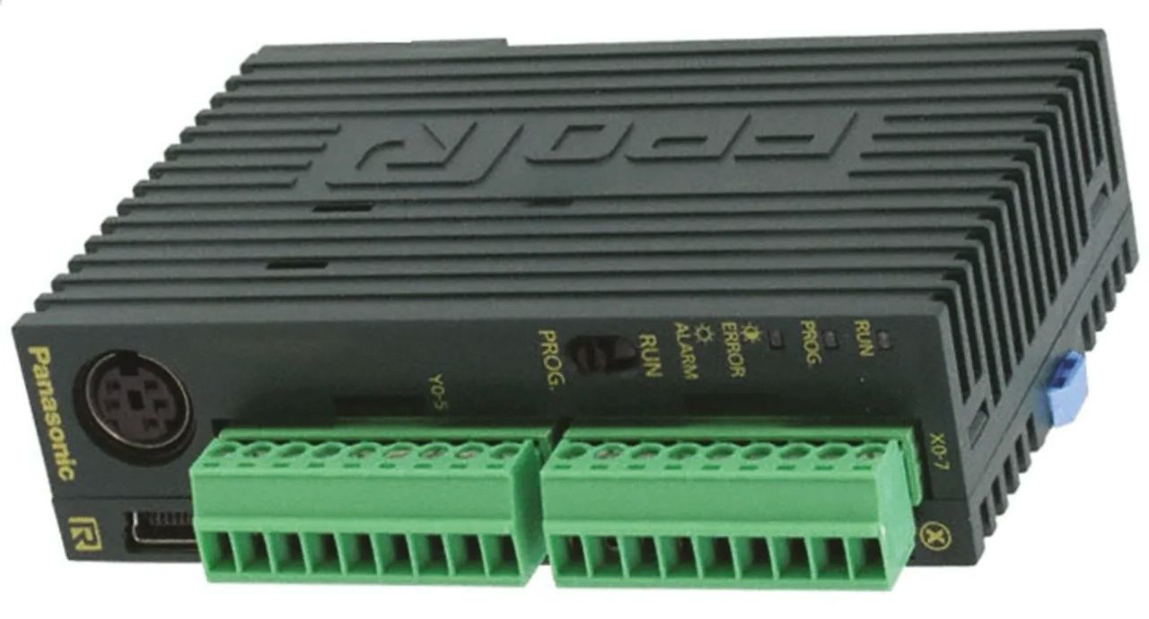
The Panasonic Programmable Logic Controller (PLC) is an industrial digital computer designed for automation and control of manufacturing processes, such as assembly lines or robotic devices. PLCs are integral to modern industrial automation, providing reliable, real-time control and monitoring of machinery and processes.
Explore Projects Built with PLC PANASONIC


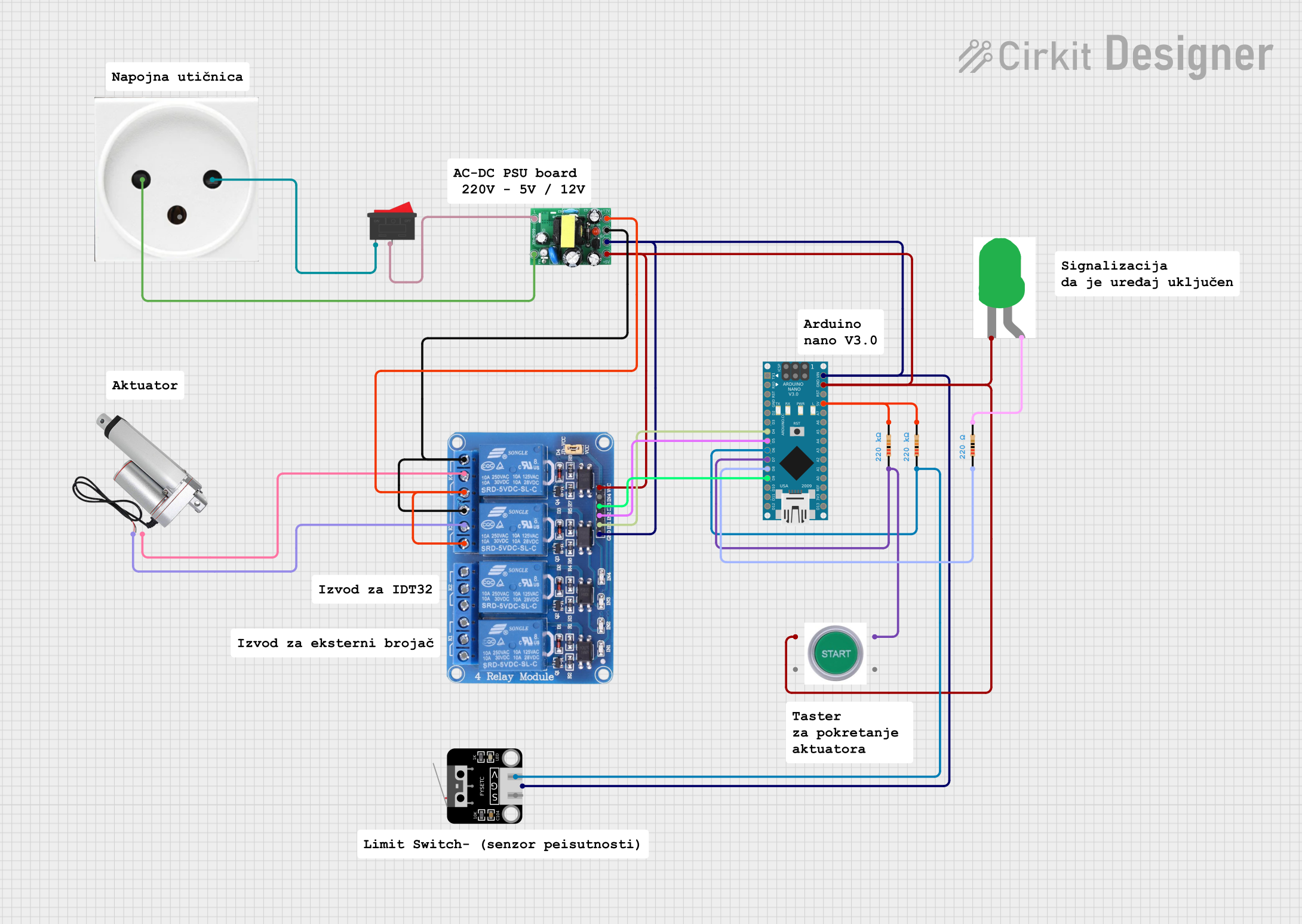
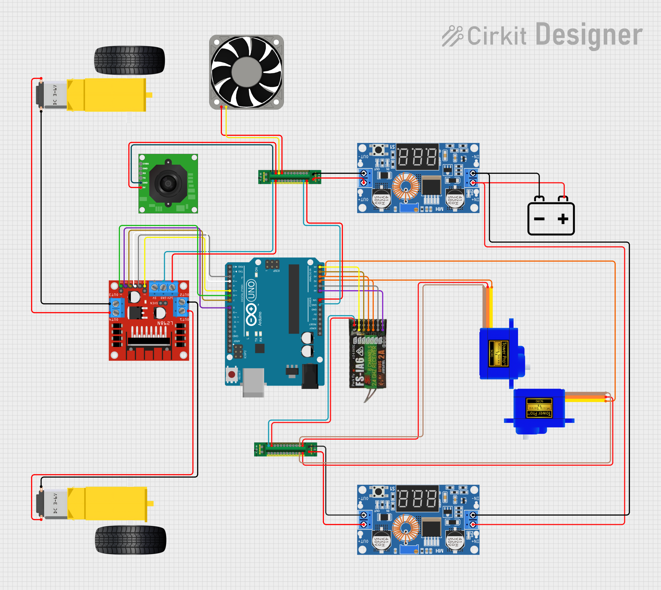
Explore Projects Built with PLC PANASONIC
Common Applications and Use Cases
- Assembly Lines: Automating the sequence of operations in manufacturing.
- Robotic Devices: Controlling robotic arms and other automated machinery.
- Process Control: Managing and monitoring industrial processes such as chemical production.
- Building Automation: Controlling HVAC, lighting, and security systems in buildings.
- Packaging Systems: Automating packaging lines for various products.
Technical Specifications
Key Technical Details
| Specification | Value |
|---|---|
| Manufacturer | Panasonic |
| Part ID | PLC |
| Power Supply | 24V DC |
| Input Voltage | 24V DC |
| Output Voltage | 24V DC |
| Input Current | 10 mA per input |
| Output Current | 0.5A per output |
| Operating Temperature | -10°C to 55°C |
| Storage Temperature | -20°C to 70°C |
| Communication Ports | RS232, RS485, Ethernet |
| Programming Language | Ladder Logic, Structured Text |
Pin Configuration and Descriptions
Input Module
| Pin Number | Description | Voltage Level |
|---|---|---|
| 1 | Input 1 | 24V DC |
| 2 | Input 2 | 24V DC |
| 3 | Input 3 | 24V DC |
| 4 | Input 4 | 24V DC |
| 5 | Common (GND) | 0V |
Output Module
| Pin Number | Description | Voltage Level |
|---|---|---|
| 1 | Output 1 | 24V DC |
| 2 | Output 2 | 24V DC |
| 3 | Output 3 | 24V DC |
| 4 | Output 4 | 24V DC |
| 5 | Common (GND) | 0V |
Usage Instructions
How to Use the Component in a Circuit
Power Supply Connection:
- Connect the 24V DC power supply to the power input terminals of the PLC.
- Ensure the polarity is correct to avoid damage.
Input Connections:
- Connect the input devices (e.g., sensors, switches) to the input module pins.
- Ensure the common ground (GND) is connected properly.
Output Connections:
- Connect the output devices (e.g., relays, actuators) to the output module pins.
- Ensure the common ground (GND) is connected properly.
Programming:
- Use the appropriate programming software to write the control logic.
- Upload the program to the PLC via the communication ports (RS232, RS485, Ethernet).
Important Considerations and Best Practices
- Power Supply: Ensure a stable and clean 24V DC power supply to avoid malfunctions.
- Grounding: Proper grounding is essential to prevent electrical noise and interference.
- Environment: Install the PLC in a well-ventilated area to avoid overheating.
- Maintenance: Regularly check connections and clean the PLC to ensure reliable operation.
Troubleshooting and FAQs
Common Issues Users Might Face
PLC Not Powering On:
- Solution: Check the power supply connections and ensure the correct voltage is supplied.
Inputs Not Responding:
- Solution: Verify the input device connections and ensure they are functioning correctly.
Outputs Not Activating:
- Solution: Check the output device connections and ensure the PLC program is correctly configured.
Communication Failure:
- Solution: Ensure the communication cables are properly connected and the correct communication settings are used.
Solutions and Tips for Troubleshooting
- Check Connections: Always start by checking all electrical connections for loose or incorrect wiring.
- Verify Power Supply: Ensure the power supply is within the specified range and stable.
- Inspect Program Logic: Review the PLC program for any logical errors or misconfigurations.
- Use Diagnostic Tools: Utilize built-in diagnostic tools and software to identify and troubleshoot issues.
Example Code for Arduino UNO Integration
/*
  Example code to interface Panasonic PLC with Arduino UNO
  using digital input and output pins.
*/

// Define the input and output pins
const int plcInputPin = 2;  // PLC input connected to Arduino pin 2
const int plcOutputPin = 3; // PLC output connected to Arduino pin 3

void setup() {
  // Initialize the input and output pins
  pinMode(plcInputPin, INPUT);
  pinMode(plcOutputPin, OUTPUT);

  // Start serial communication for debugging
  Serial.begin(9600);
}

void loop() {
  // Read the state of the PLC input
  int plcInputState = digitalRead(plcInputPin);

  // Print the input state to the serial monitor
  Serial.print("PLC Input State: ");
  Serial.println(plcInputState);

  // Control the PLC output based on the input state
  if (plcInputState == HIGH) {
    digitalWrite(plcOutputPin, HIGH); // Activate the output
  } else {
    digitalWrite(plcOutputPin, LOW);  // Deactivate the output
  }

  // Add a small delay to avoid rapid state changes
  delay(100);
}
This example demonstrates how to interface a Panasonic PLC with an Arduino UNO using digital input and output pins. The Arduino reads the state of a PLC input and controls a PLC output accordingly.
By following this documentation, users can effectively utilize the Panasonic PLC in various industrial automation applications, ensuring reliable and efficient control of manufacturing processes.