Cirkit Designer Logo
Cirkit Designer
Your all-in-one circuit design IDE
Home / 
Component Documentation

How to Use Voltmeter: Examples, Pinouts, and Specs

Image of Voltmeter
Cirkit Designer LogoDesign with Voltmeter in Cirkit Designer

Introduction

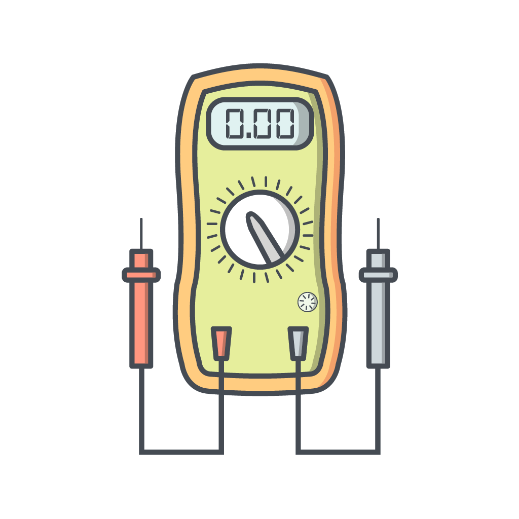
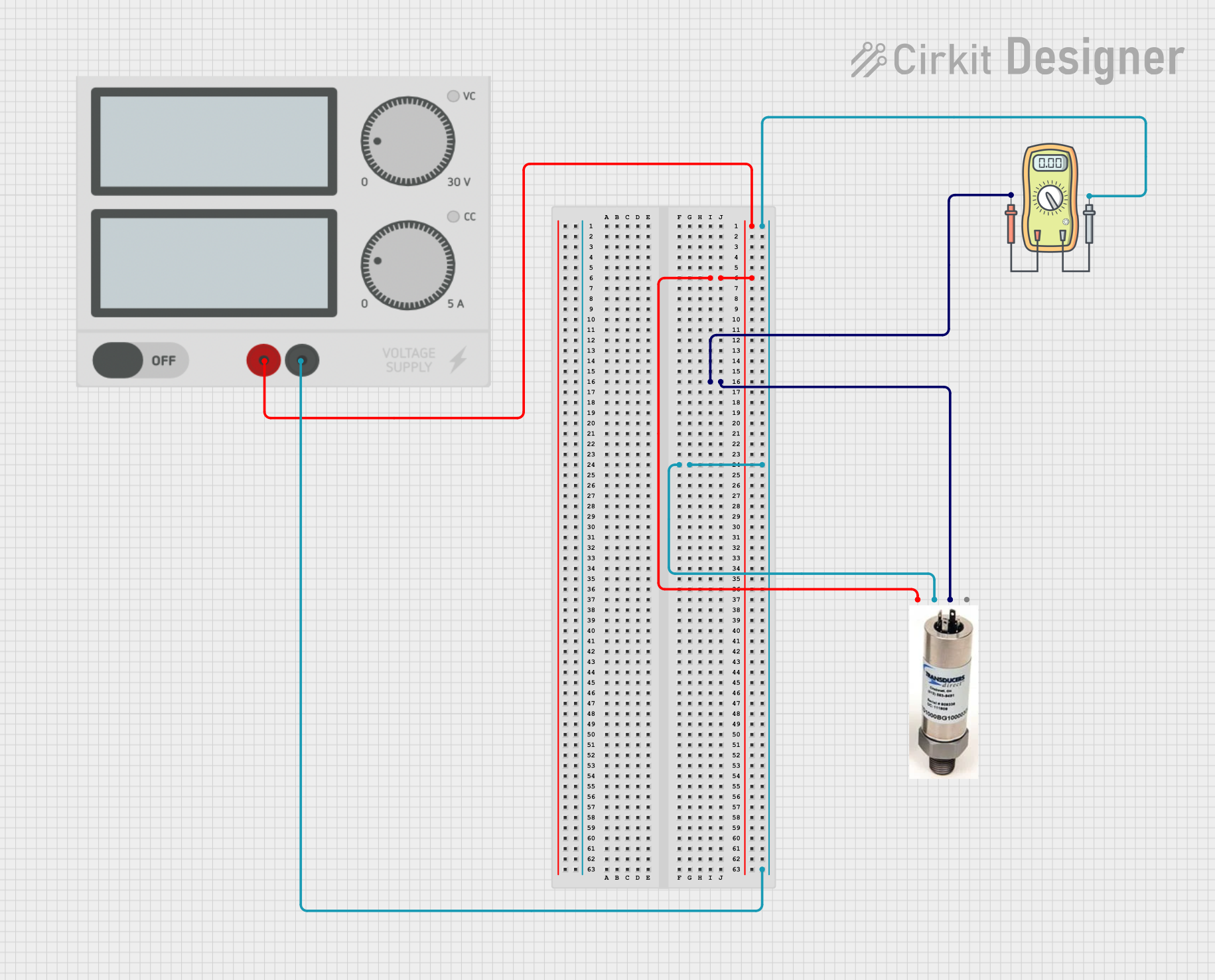
A voltmeter is an instrument used for measuring the electrical potential difference between two points in an electric circuit. It is an essential tool for anyone working with electronics, from hobbyists to professional engineers. Voltmeters can be analog or digital, with digital voltmeters (DVMs) being more common due to their higher accuracy and ease of use.

Explore Projects Built with Voltmeter

Use Cirkit Designer to design, explore, and prototype these projects online. Some projects support real-time simulation. Click "Open Project" to start designing instantly!
Battery-Powered LED Circuit with Digital Volt/Ammeter
Image of Simple: A project utilizing Voltmeter in a practical application
This circuit consists of a 9V battery powering a red LED, with a Mini Digital Volt/Ammeter connected to measure the voltage supplied to the LED. The anode of the LED is connected to the positive terminal of the battery through the voltmeter, and the cathode is connected to the negative terminal of the battery through the ground pin of the voltmeter.
Cirkit Designer LogoOpen Project in Cirkit Designer
DC Voltage Measurement Circuit with LM393 and Digital Volt/Ammeter
Image of Simple: A project utilizing Voltmeter in a practical application
This circuit consists of a DC power source connected to a mini digital volt/ammeter. The volt/ammeter measures the voltage supplied by the DC power source, with the ground and positive terminals of the power source connected to the corresponding ground and voltage reading pins of the volt/ammeter.
Cirkit Designer LogoOpen Project in Cirkit Designer
Pressure Monitoring System with Voltmeter and Power Supply
Image of PT Test: A project utilizing Voltmeter in a practical application
This circuit measures the output voltage of a pressure transducer using a voltmeter. The pressure transducer is powered by a power supply, and its output voltage is connected to the voltmeter for measurement.
Cirkit Designer LogoOpen Project in Cirkit Designer
Arduino UNO Power Meter with I2C LCD Display and Current/Voltage Sensors
Image of Arduino UNO Simulator: A project utilizing Voltmeter in a practical application
This circuit is a power measurement system using an Arduino UNO, which reads voltage and current values from a voltage sensor and a current sensor, respectively. The measured values are displayed on a 16x2 I2C LCD and also sent to the serial monitor for debugging. Additionally, an LED is included for visual indication, and a 9V battery powers the entire setup.
Cirkit Designer LogoOpen Project in Cirkit Designer

Explore Projects Built with Voltmeter

Use Cirkit Designer to design, explore, and prototype these projects online. Some projects support real-time simulation. Click "Open Project" to start designing instantly!
Image of Simple: A project utilizing Voltmeter in a practical application
Battery-Powered LED Circuit with Digital Volt/Ammeter
This circuit consists of a 9V battery powering a red LED, with a Mini Digital Volt/Ammeter connected to measure the voltage supplied to the LED. The anode of the LED is connected to the positive terminal of the battery through the voltmeter, and the cathode is connected to the negative terminal of the battery through the ground pin of the voltmeter.
Cirkit Designer LogoOpen Project in Cirkit Designer
Image of Simple: A project utilizing Voltmeter in a practical application
DC Voltage Measurement Circuit with LM393 and Digital Volt/Ammeter
This circuit consists of a DC power source connected to a mini digital volt/ammeter. The volt/ammeter measures the voltage supplied by the DC power source, with the ground and positive terminals of the power source connected to the corresponding ground and voltage reading pins of the volt/ammeter.
Cirkit Designer LogoOpen Project in Cirkit Designer
Image of PT Test: A project utilizing Voltmeter in a practical application
Pressure Monitoring System with Voltmeter and Power Supply
This circuit measures the output voltage of a pressure transducer using a voltmeter. The pressure transducer is powered by a power supply, and its output voltage is connected to the voltmeter for measurement.
Cirkit Designer LogoOpen Project in Cirkit Designer
Image of Arduino UNO Simulator: A project utilizing Voltmeter in a practical application
Arduino UNO Power Meter with I2C LCD Display and Current/Voltage Sensors
This circuit is a power measurement system using an Arduino UNO, which reads voltage and current values from a voltage sensor and a current sensor, respectively. The measured values are displayed on a 16x2 I2C LCD and also sent to the serial monitor for debugging. Additionally, an LED is included for visual indication, and a 9V battery powers the entire setup.
Cirkit Designer LogoOpen Project in Cirkit Designer

Common Applications and Use Cases

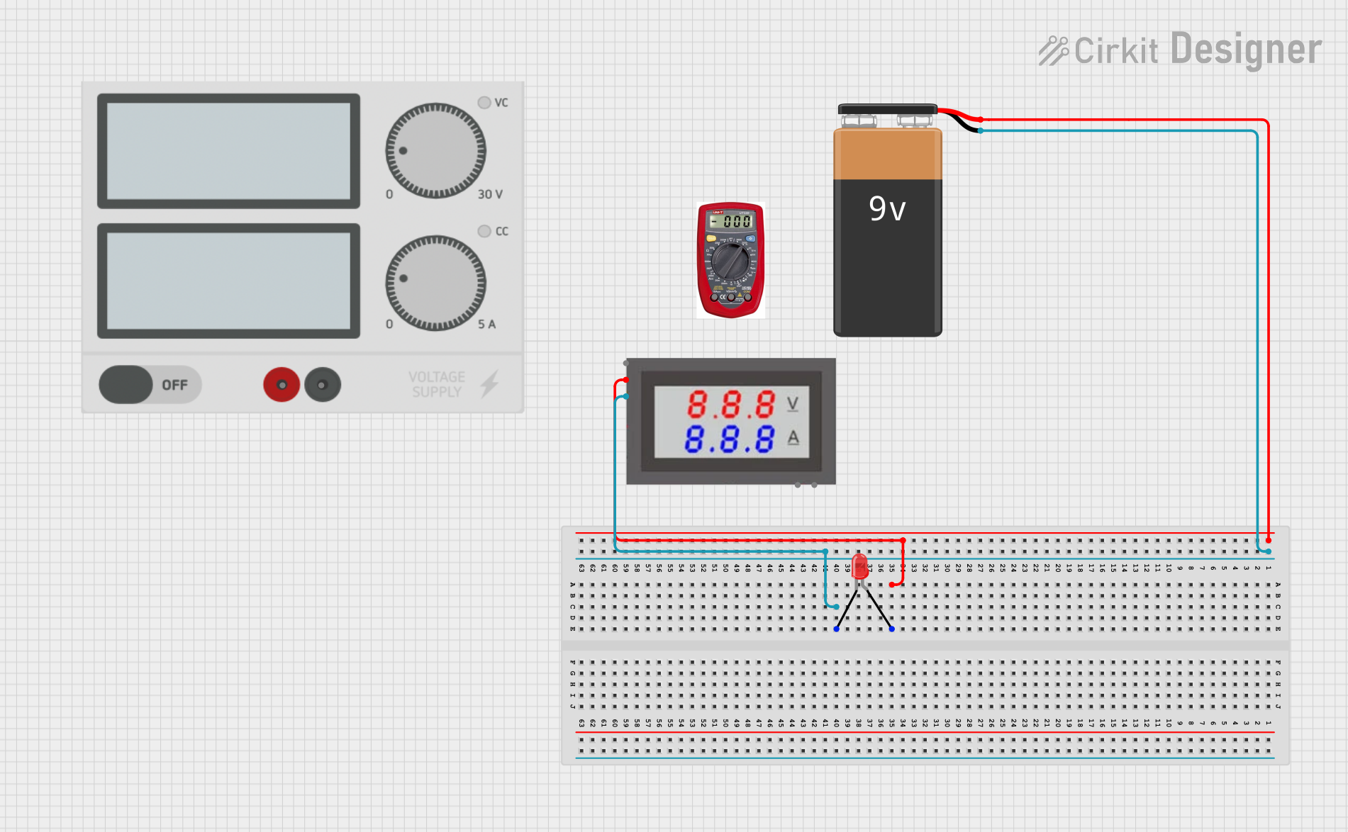
  • Circuit Testing: To verify the voltage levels in various parts of a circuit.
  • Battery Testing: To check the voltage of batteries to determine their charge level.
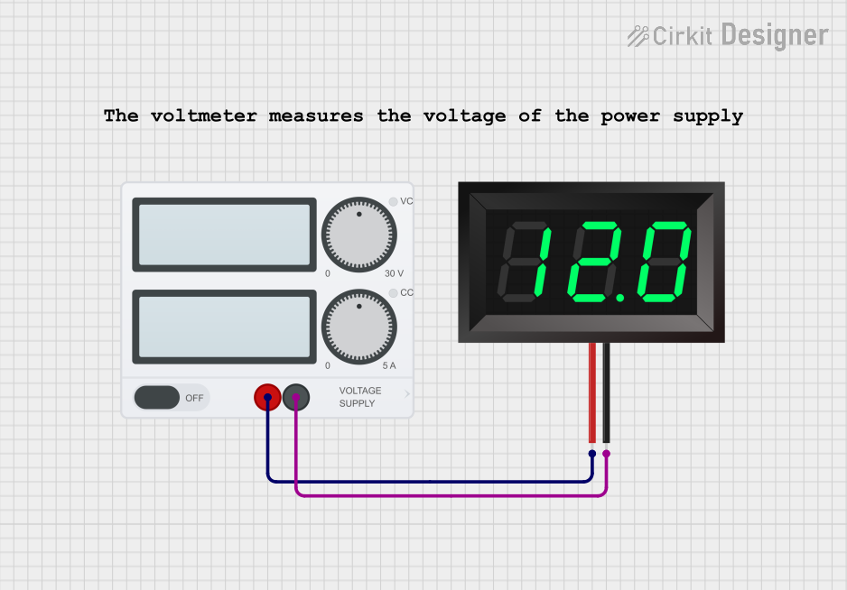
  • Power Supply Monitoring: To ensure that power supplies are providing the correct voltage.
  • Troubleshooting: To diagnose issues in electronic circuits by checking voltage levels.

Technical Specifications

Key Technical Details

Specification Value
Voltage Range 0 - 600V (varies by model)
Accuracy ±0.5% of reading
Display Type Digital (LCD/LED)
Input Impedance 10 MΩ
Power Supply 9V Battery or External Power
Dimensions 150mm x 70mm x 30mm
Weight 200g

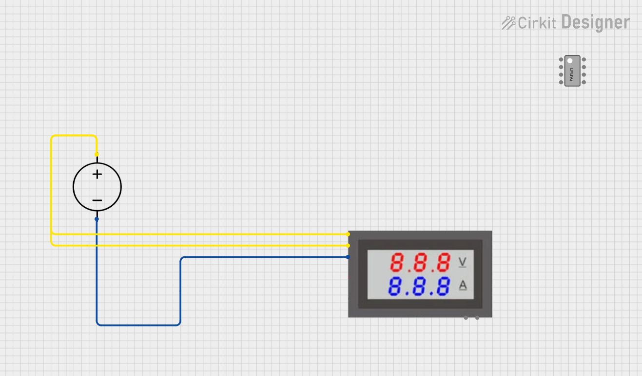
Pin Configuration and Descriptions

Pin Number Pin Name Description
1 V+ Positive voltage input
2 V- Negative voltage input (ground)
3 COM Common ground (for external power supply)
4 Vcc Positive power supply input (for external power)

Usage Instructions

How to Use the Voltmeter in a Circuit

  1. Powering the Voltmeter:

    • If using a battery, insert a 9V battery into the battery compartment.
    • If using an external power supply, connect the positive terminal to the Vcc pin and the negative terminal to the COM pin.
  2. Connecting to the Circuit:

    • Connect the V+ pin to the point in the circuit where you want to measure the voltage.
    • Connect the V- pin to the ground or reference point in the circuit.
  3. Reading the Voltage:

    • Turn on the voltmeter.
    • The voltage reading will be displayed on the screen.

Important Considerations and Best Practices

  • Polarity: Ensure correct polarity when connecting the voltmeter to avoid damage.
  • Range Selection: If your voltmeter has multiple ranges, select the appropriate range for the voltage you expect to measure.
  • Input Impedance: High input impedance is crucial to avoid loading the circuit and affecting the measurement.
  • Safety: Always follow safety guidelines, especially when measuring high voltages.

Troubleshooting and FAQs

Common Issues and Solutions

  1. No Display or Incorrect Reading:

    • Solution: Check the power supply (battery or external). Ensure proper connections and that the battery is not depleted.
  2. Fluctuating Readings:

    • Solution: Ensure stable connections. Fluctuations can be caused by loose connections or interference.
  3. Overload Indication:

    • Solution: If the voltmeter displays an overload indication, switch to a higher voltage range.

FAQs

Q1: Can I use the voltmeter to measure AC voltage?

  • A1: Yes, but ensure your voltmeter is rated for AC voltage measurement and select the appropriate mode.

Q2: What should I do if the voltmeter shows a negative reading?

  • A2: This indicates that the polarity is reversed. Swap the V+ and V- connections.

Q3: How often should I calibrate my voltmeter?

  • A3: Calibration frequency depends on usage, but generally, it should be calibrated annually for accurate measurements.

Example Code for Arduino UNO

If you are using a digital voltmeter module with an Arduino UNO, you can use the following example code to read and display the voltage:

// Define the analog pin where the voltmeter is connected
const int voltmeterPin = A0;

void setup() {
  // Initialize serial communication at 9600 baud rate
  Serial.begin(9600);
}

void loop() {
  // Read the analog value from the voltmeter pin
  int sensorValue = analogRead(voltmeterPin);
  
  // Convert the analog value to voltage
  // Assuming a 5V reference voltage and 10-bit ADC (0-1023)
  float voltage = sensorValue * (5.0 / 1023.0);
  
  // Print the voltage to the serial monitor
  Serial.print("Voltage: ");
  Serial.print(voltage);
  Serial.println(" V");
  
  // Wait for 1 second before taking another reading
  delay(1000);
}

This code reads the voltage from an analog pin connected to the voltmeter and prints the value to the serial monitor. Ensure that the voltmeter module is properly connected to the Arduino UNO.

By following this documentation, users can effectively utilize a voltmeter in various applications, ensuring accurate and reliable voltage measurements.