How to Use Momentary Push Button Switch: Examples, Pinouts, and Specs
Introduction
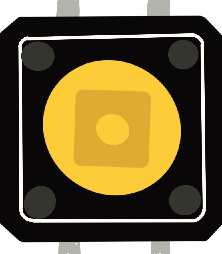
The RUNCCI-YUN TS-G005 is a momentary push button switch designed for a wide range of applications. This switch is commonly used in electronic projects and commercial products for simple on/off control, user input, or as an interface for user interaction. Due to its momentary action, the switch is only active when pressed and returns to its inactive state upon release.
Explore Projects Built with Momentary Push Button Switch
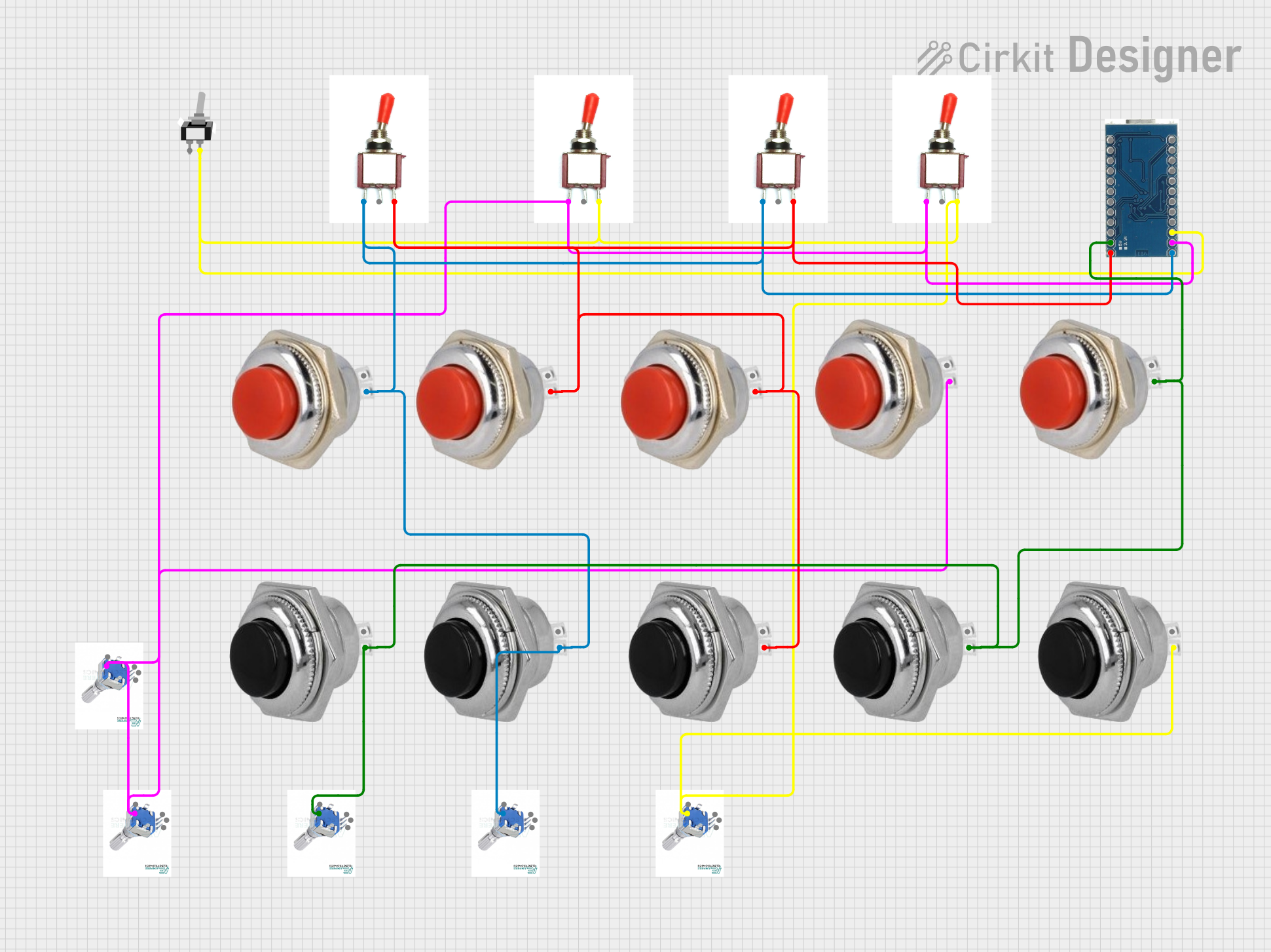
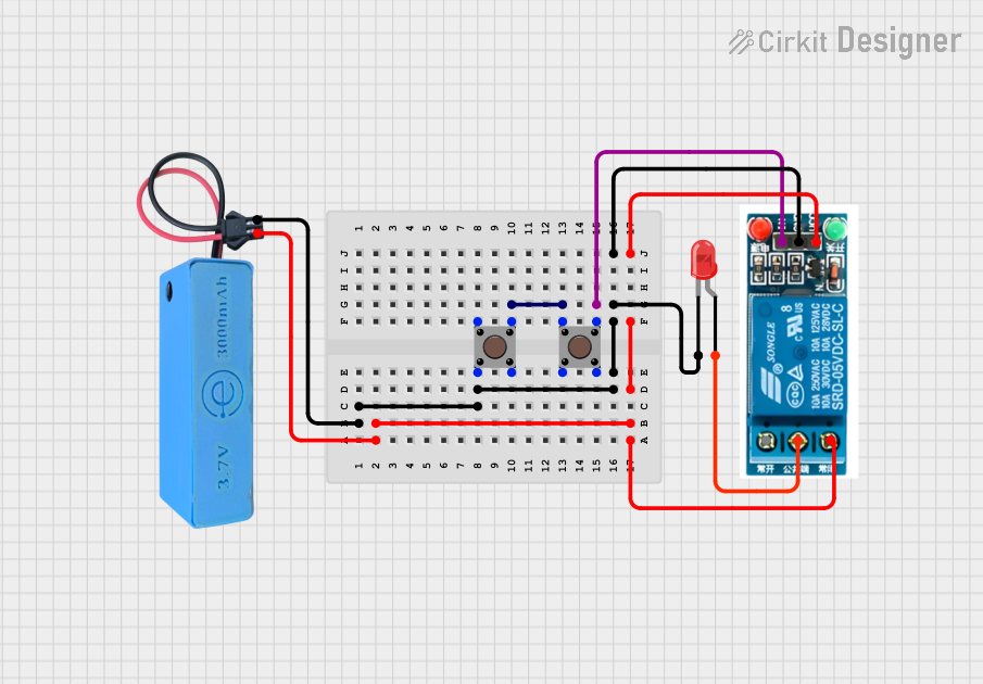
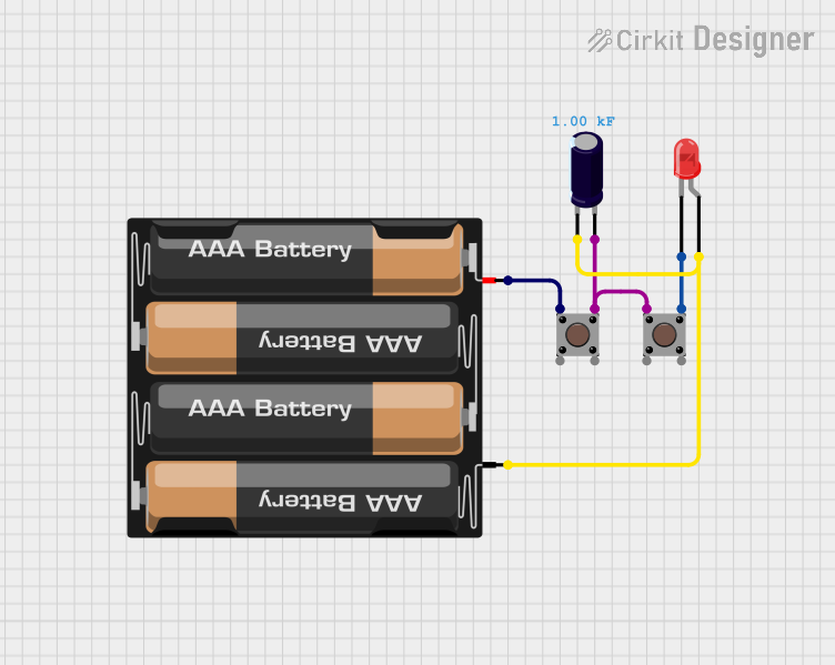

Explore Projects Built with Momentary Push Button Switch
Common Applications
- User interfaces
- Control panels
- Hobbyist projects, including Arduino-based devices
- Industrial controls
Technical Specifications
Key Technical Details
- Switch Type: Momentary Push Button
- Contact Configuration: Normally Open (NO)
- Material: Plastic and Metal
- Contact Rating: 3A @ 125V AC, 1.5A @ 250V AC
- Operation Type: Momentary
- Mounting Type: Through-Hole
- Termination Style: Solder Lug
Pin Configuration and Descriptions
| Pin Number | Description |
|---|---|
| 1 | Normally Open (NO) |
| 2 | Common (COM) |
Usage Instructions
How to Use in a Circuit
- Mounting: Insert the switch into the designated through-hole slots on your PCB or breadboard.
- Soldering: Solder the pins to ensure a secure and reliable electrical connection.
- Wiring: Connect one terminal to the input line (e.g., power or signal) and the other to the load (e.g., LED, relay, or microcontroller input pin).
- Operation: Press the button to momentarily close the circuit, allowing current to flow.
Important Considerations and Best Practices
- Ensure the power rating does not exceed the switch's maximum rating to avoid damage.
- Use a pull-down or pull-up resistor when connecting to a microcontroller to ensure a stable signal.
- Avoid excessive force when pressing the switch to prevent mechanical damage.
Example Code for Arduino UNO
// Define the pin connected to the push button
const int buttonPin = 2;
// Variable for reading the push button status
int buttonState = 0;

void setup() {
  // Initialize the push button pin as an input
  pinMode(buttonPin, INPUT);
}

void loop() {
  // Read the state of the push button value
  buttonState = digitalRead(buttonPin);

  // Check if the push button is pressed
  // if it is, the buttonState is HIGH
  if (buttonState == HIGH) {
    // Turn on an LED (or perform another action)
  } else {
    // Turn off the LED (or stop the action)
  }
}
Troubleshooting and FAQs
Common Issues
- Switch does not respond: Ensure the switch is properly soldered and there are no loose connections.
- Intermittent operation: Check for any physical damage to the switch or debris that may prevent proper operation.
Solutions and Tips
- Debouncing: Implement software debouncing in your code to prevent false triggering due to switch bounce.
- Secure Mounting: Ensure the switch is mounted securely to prevent movement that could cause intermittent connections.
FAQs
Q: Can I use this switch with a higher voltage or current? A: No, exceeding the specified voltage or current ratings can damage the switch and lead to unsafe conditions.
Q: How can I tell if the switch is in the ON or OFF position? A: As a momentary switch, it is only ON when pressed. It returns to OFF when released.
Q: What is the lifespan of the switch? A: The lifespan depends on usage, but it is typically rated for thousands of cycles.
Remember to always follow safety guidelines when working with electronic components and consult the manufacturer's datasheet for more detailed information.