How to Use 8CH BI-DIRECTIONAL: Examples, Pinouts, and Specs
Introduction
The 8-channel bi-directional switch (8CH BI-DIRECTIONAL) is a versatile electronic component designed to allow signals to flow in both directions across eight independent channels. This functionality makes it ideal for applications requiring flexible signal routing, such as audio, video, and data communication systems. The component is commonly used in multiplexing, signal switching, and bidirectional data transfer scenarios.
Explore Projects Built with 8CH BI-DIRECTIONAL

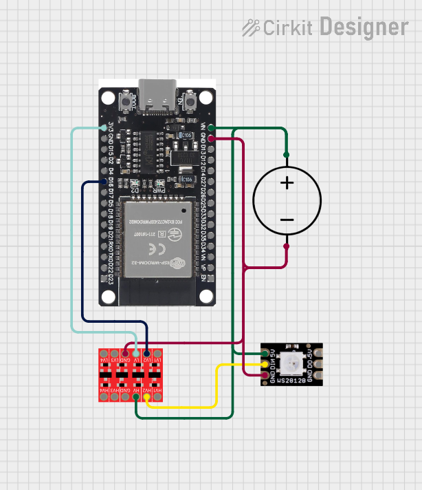

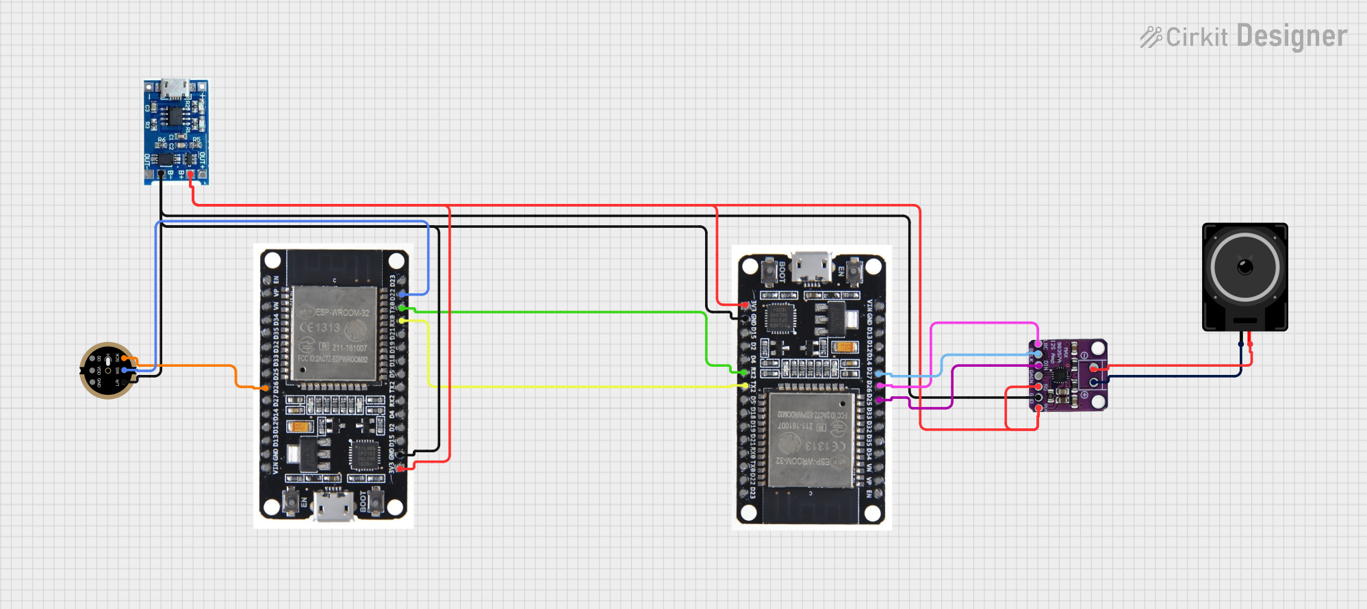
Explore Projects Built with 8CH BI-DIRECTIONAL
Common Applications and Use Cases
- Audio signal routing in mixers and amplifiers
- Video signal switching in multimedia systems
- Data communication in microcontroller-based projects
- Multiplexing and demultiplexing in digital circuits
- Signal routing in test and measurement equipment
Technical Specifications
The 8CH BI-DIRECTIONAL switch is designed to handle a wide range of signals with minimal distortion or loss. Below are the key technical details:
General Specifications
- Number of Channels: 8
- Signal Direction: Bi-directional
- Operating Voltage: 3.3V to 5V DC
- Maximum Signal Voltage: 12V
- Maximum Signal Frequency: 10 MHz
- On-Resistance (RON): Typically 10Ω
- Control Logic Voltage: 3.3V or 5V (TTL compatible)
- Power Consumption: Low power operation (<1 mW per channel)
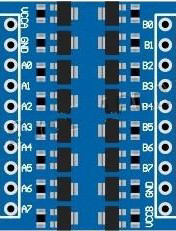
Pin Configuration and Descriptions
The 8CH BI-DIRECTIONAL switch typically comes in a 16-pin package. Below is the pinout and description:
| Pin Number | Pin Name | Description |
|---|---|---|
| 1 | IN1 | Input/Output for Channel 1 |
| 2 | OUT1 | Output/Input for Channel 1 |
| 3 | IN2 | Input/Output for Channel 2 |
| 4 | OUT2 | Output/Input for Channel 2 |
| 5 | IN3 | Input/Output for Channel 3 |
| 6 | OUT3 | Output/Input for Channel 3 |
| 7 | IN4 | Input/Output for Channel 4 |
| 8 | OUT4 | Output/Input for Channel 4 |
| 9 | IN5 | Input/Output for Channel 5 |
| 10 | OUT5 | Output/Input for Channel 5 |
| 11 | IN6 | Input/Output for Channel 6 |
| 12 | OUT6 | Output/Input for Channel 6 |
| 13 | IN7 | Input/Output for Channel 7 |
| 14 | OUT7 | Output/Input for Channel 7 |
| 15 | IN8 | Input/Output for Channel 8 |
| 16 | OUT8 | Output/Input for Channel 8 |
Usage Instructions
How to Use the Component in a Circuit
- Power Supply: Connect the VCC pin of the 8CH BI-DIRECTIONAL switch to a 3.3V or 5V DC power source, depending on your system's logic level. Connect the GND pin to the ground of your circuit.
- Signal Connections: Connect the input signals to the
INpins and the corresponding output devices to theOUTpins. The switch allows signals to flow in either direction, so the roles ofINandOUTcan be interchanged. - Control Logic: If the switch includes control pins, ensure they are properly configured to enable or disable specific channels as needed. Refer to the datasheet for control logic details.
Important Considerations and Best Practices
- Signal Voltage: Ensure the signal voltage does not exceed the maximum rating of 12V to avoid damaging the component.
- Frequency Limitations: For high-frequency signals, ensure the signal frequency is within the 10 MHz limit to maintain signal integrity.
- On-Resistance: Be aware of the on-resistance (RON) of the switch, as it can introduce a small voltage drop in the signal path.
- Decoupling Capacitors: Place decoupling capacitors (e.g., 0.1 µF) near the power supply pins to reduce noise and ensure stable operation.
Example: Connecting to an Arduino UNO
The 8CH BI-DIRECTIONAL switch can be controlled using an Arduino UNO. Below is an example of how to use the switch to route signals:
Circuit Setup
- Connect the
IN1pin to a signal source (e.g., a sensor or audio input). - Connect the
OUT1pin to a load (e.g., an LED or speaker). - Use a digital pin on the Arduino to control the switch (if applicable).
Arduino Code Example
// Example code to control an 8CH BI-DIRECTIONAL switch with Arduino UNO

const int controlPin = 7; // Pin connected to the control input of the switch

void setup() {
  pinMode(controlPin, OUTPUT); // Set the control pin as an output
  digitalWrite(controlPin, LOW); // Initialize the switch to OFF state
}

void loop() {
  // Turn the switch ON
  digitalWrite(controlPin, HIGH);
  delay(1000); // Keep the switch ON for 1 second

  // Turn the switch OFF
  digitalWrite(controlPin, LOW);
  delay(1000); // Keep the switch OFF for 1 second
}
Troubleshooting and FAQs
Common Issues and Solutions
No Signal Output:
- Cause: Incorrect wiring or control logic.
- Solution: Double-check the connections and ensure the control pins are properly configured.
Signal Distortion:
- Cause: Exceeding the frequency or voltage limits.
- Solution: Verify that the signal frequency is below 10 MHz and the voltage is within the 12V limit.
Excessive Heat:
- Cause: Overloading the switch with high current.
- Solution: Ensure the current through each channel does not exceed the component's rating.
Intermittent Operation:
- Cause: Power supply instability or noise.
- Solution: Add decoupling capacitors near the power supply pins.
FAQs
Q1: Can the 8CH BI-DIRECTIONAL switch handle analog signals?
A1: Yes, the switch can handle both analog and digital signals, provided the signal voltage and frequency are within the specified limits.
Q2: Can I use the switch for I2C communication?
A2: Yes, the switch can be used for I2C communication, as it supports bidirectional data flow. Ensure the pull-up resistors are properly configured.
Q3: What happens if I exceed the maximum signal voltage?
A3: Exceeding the maximum signal voltage can damage the switch. Always ensure the signal voltage is within the specified range.
Q4: Is the switch suitable for high-speed data communication?
A4: The switch supports signals up to 10 MHz. For higher-speed applications, consider using a component with a higher frequency rating.