How to Use Adafruit H3LIS331 Triple-Axis Accelerometer: Examples, Pinouts, and Specs
Introduction
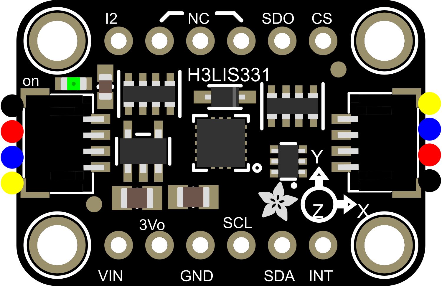
The Adafruit H3LIS331 Triple-Axis Accelerometer is a versatile and powerful sensor capable of measuring acceleration along three axes: X, Y, and Z. This low-power, high-performance module is based on the H3LIS331DL IC from STMicroelectronics and is designed for a wide array of applications, from motion detection to dynamic orientation tracking. Its wide measurement range and adjustable sensitivity make it an excellent choice for projects ranging from robotics to sports equipment.
Explore Projects Built with Adafruit H3LIS331 Triple-Axis Accelerometer
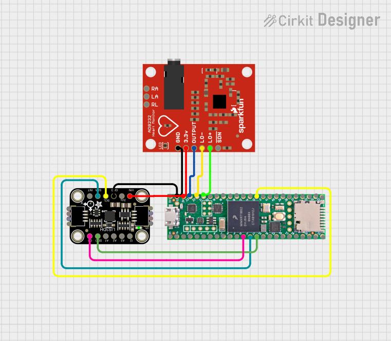
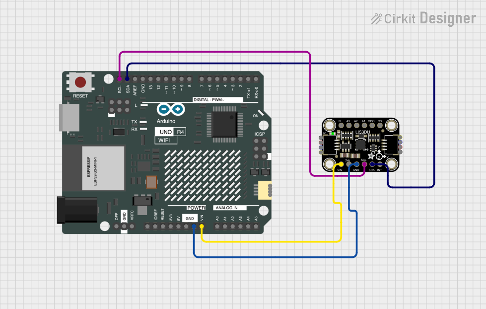
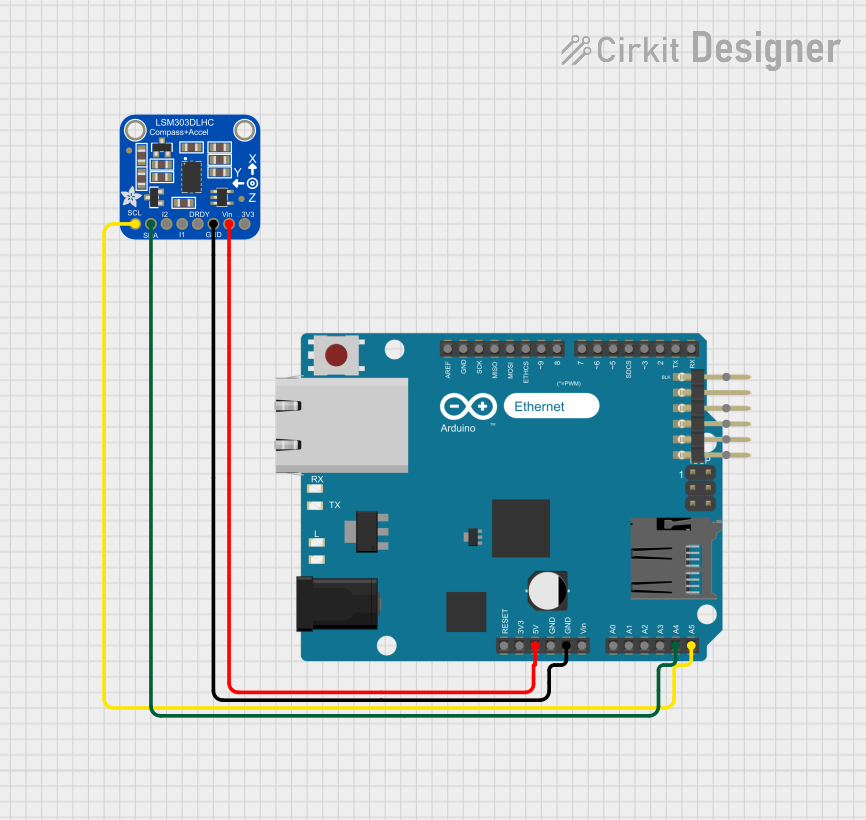

Explore Projects Built with Adafruit H3LIS331 Triple-Axis Accelerometer
Common Applications and Use Cases
- Vibration monitoring and analysis
- Impact and collision detection
- Inertial measurement units (IMUs) for orientation and motion tracking
- Activity monitoring in wearable devices
- Gaming and virtual reality input devices
- Vehicle dynamics and telematics
Technical Specifications
Key Technical Details
- Voltage Supply: 2.16V to 3.6V
- Current Consumption: 300 µA (typical)
- Measurement Range: ±100g, ±200g, ±400g (selectable)
- Sensitivity: Adjustable via software
- Output Data Rates (ODR): Up to 1 kHz
- Interface: I2C (up to 400 kHz)
- Operating Temperature Range: -40°C to +85°C
Pin Configuration and Descriptions
| Pin Number | Pin Name | Description |
|---|---|---|
| 1 | VDD | Power supply (2.16V to 3.6V) |
| 2 | GND | Ground |
| 3 | SCL | I2C Serial Clock Line |
| 4 | SDA | I2C Serial Data Line |
| 5 | INT1 | Interrupt 1 (configurable) |
| 6 | INT2 | Interrupt 2 (configurable) |
| 7 | CS | Chip Select for SPI (not used in I2C mode) |
| 8 | SA0 | I2C Least Significant Bit of the device address |
Usage Instructions
How to Use the Component in a Circuit
- Powering the Device: Connect the VDD pin to a power supply between 2.16V and 3.6V, and connect the GND pin to the ground of your circuit.
- I2C Communication: Connect the SCL and SDA pins to the corresponding I2C clock and data lines on your microcontroller, such as an Arduino UNO.
- Address Selection: The SA0 pin determines the least significant bit of the I2C address. Connect it to VDD or GND to select between the two possible addresses.
- Interrupts (Optional): The INT1 and INT2 pins can be configured to output interrupt signals for certain events. Connect these to digital pins on your microcontroller if you wish to use interrupts.
Important Considerations and Best Practices
- Ensure that the power supply is within the specified voltage range to prevent damage.
- Use pull-up resistors on the I2C lines if they are not already present on your microcontroller board.
- Configure the accelerometer's range and sensitivity to match the expected acceleration in your application.
- Place the accelerometer as close as possible to the center of mass of the object being measured for accurate readings.
- Avoid physical shocks and vibrations during soldering and handling that could affect the sensor's calibration.
Example Code for Arduino UNO
#include <Wire.h>

// Adafruit H3LIS331 I2C address (assuming SA0 is connected to GND)
#define ACCEL_I2C_ADDR 0x18

void setup() {
  Wire.begin(); // Initialize I2C
  Serial.begin(9600); // Start serial communication at 9600 baud

  // Configure accelerometer settings
  writeAccelRegister(0x20, 0x27); // Normal power mode, 50Hz data rate
  writeAccelRegister(0x23, 0x00); // Continuous update, LSB at lower address, ±100g
}

void loop() {
  int16_t x, y, z;

  // Read acceleration data
  x = readAccel(0x28);
  y = readAccel(0x2A);
  z = readAccel(0x2C);

  // Print the acceleration values
  Serial.print("X: ");
  Serial.print(x);
  Serial.print(" Y: ");
  Serial.print(y);
  Serial.print(" Z: ");
  Serial.println(z);

  delay(100); // Wait for 100 milliseconds
}

void writeAccelRegister(byte reg, byte value) {
  // Write a value to a register on the accelerometer
  Wire.beginTransmission(ACCEL_I2C_ADDR);
  Wire.write(reg);
  Wire.write(value);
  Wire.endTransmission();
}

int16_t readAccel(byte reg) {
  // Read a 16-bit value from a register on the accelerometer
  Wire.beginTransmission(ACCEL_I2C_ADDR);
  Wire.write(reg | 0x80); // Set auto increment bit
  Wire.endTransmission(false);
  Wire.requestFrom(ACCEL_I2C_ADDR, 2, true);

  byte lowByte = Wire.read();
  byte highByte = Wire.read();

  return (int16_t)(highByte << 8 | lowByte);
}
Troubleshooting and FAQs
Common Issues
- No Data or Erratic Readings: Ensure that the I2C connections are secure and that pull-up resistors are in place. Check the power supply voltage.
- Incorrect Readings: Verify that the accelerometer's range and sensitivity settings are correctly configured for your application.
Solutions and Tips for Troubleshooting
- Double-check wiring and solder joints for any loose connections or shorts.
- Use a multimeter to verify the voltage levels at the VDD and GND pins.
- If using interrupts, ensure that the INT1 and INT2 pins are correctly configured and handled in your code.
- Implement a simple I2C scanner sketch to ensure that the accelerometer is detected on the I2C bus.
FAQs
Q: Can the accelerometer be used with a 5V microcontroller like the Arduino UNO? A: Yes, but ensure that the VDD pin is connected to a voltage within the specified range, and use level shifters if necessary for the I2C lines.
Q: How can I change the measurement range? A: The measurement range can be changed by writing to the CTRL_REG4 (0x23) register. Refer to the datasheet for the appropriate settings.
Q: What is the default I2C address? A: The default I2C address is 0x18 when SA0 is connected to GND, and 0x19 when SA0 is connected to VDD.