How to Use ESP32 (30 pin): Examples, Pinouts, and Specs
Introduction
The ESP32 is a powerful microcontroller with built-in Wi-Fi and Bluetooth capabilities, making it an excellent choice for Internet of Things (IoT) applications and embedded systems. With its 30-pin configuration, the ESP32 offers a wide range of input/output (I/O) options, including digital, analog, PWM, and communication interfaces such as UART, SPI, and I2C. Its dual-core processor and low-power modes make it suitable for both high-performance and energy-efficient applications.
Explore Projects Built with ESP32 (30 pin)


Explore Projects Built with ESP32 (30 pin)
Common Applications and Use Cases
- IoT devices and smart home automation
- Wireless sensor networks
- Wearable technology
- Robotics and automation systems
- Data logging and remote monitoring
- Prototyping and educational projects
Technical Specifications
The ESP32 (30 pin) microcontroller is packed with features that make it versatile and powerful. Below are its key technical specifications:
Key Technical Details
- Processor: Dual-core Xtensa® 32-bit LX6 CPU
- Clock Speed: Up to 240 MHz
- Flash Memory: 4 MB (varies by model)
- SRAM: 520 KB
- Wi-Fi: 802.11 b/g/n
- Bluetooth: v4.2 BR/EDR and BLE
- Operating Voltage: 3.3V
- Input Voltage Range: 5V (via USB) or 3.3V (via VIN pin)
- GPIO Pins: 30 pins (including digital, analog, and communication interfaces)
- ADC Resolution: 12-bit
- DAC Resolution: 8-bit
- PWM Channels: 16
- Communication Protocols: UART, SPI, I2C, CAN, I2S
- Power Consumption: Ultra-low power modes available
- Operating Temperature: -40°C to 125°C
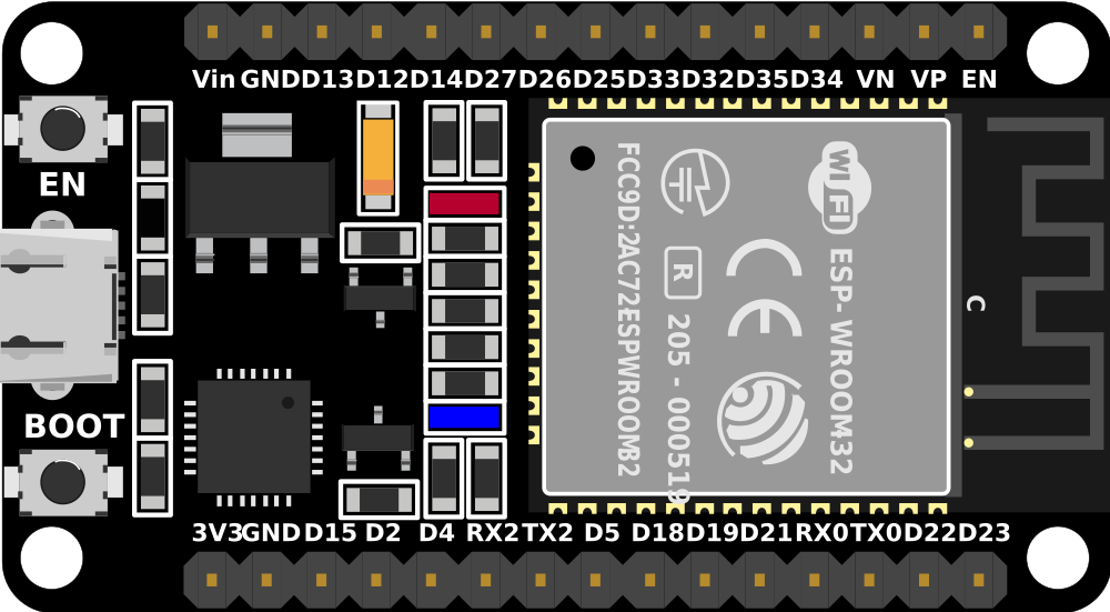
Pin Configuration and Descriptions
The ESP32 (30 pin) has a variety of pins for different functionalities. Below is a table summarizing the pin configuration:
| Pin Name | Function | Description |
|---|---|---|
| VIN | Power Input | Input voltage (5V) for powering the ESP32 via an external source. |
| GND | Ground | Ground connection. |
| 3V3 | Power Output | Provides 3.3V output for external components. |
| EN | Enable | Enables or disables the chip. Active high. |
| IO0 | GPIO0 / Boot Mode Selection | General-purpose I/O pin. Used for boot mode selection during programming. |
| IO1-IO39 | GPIO Pins | General-purpose I/O pins. Some support ADC, PWM, I2C, SPI, or UART functions. |
| ADC1/ADC2 | Analog Input | 12-bit ADC channels for analog-to-digital conversion. |
| DAC1/DAC2 | Digital-to-Analog Converter | 8-bit DAC channels for analog output. |
| TXD0/RXD0 | UART0 TX/RX | UART communication pins for serial data transmission and reception. |
| SCL/SDA | I2C Clock/Data | I2C communication pins for interfacing with sensors and peripherals. |
| MOSI/MISO | SPI Data | SPI communication pins for data transmission and reception. |
| SCK | SPI Clock | SPI clock pin for synchronous communication. |
| A0-A19 | Analog/Digital I/O | Multipurpose pins for analog or digital input/output. |
Usage Instructions
The ESP32 (30 pin) is easy to use in a variety of circuits. Below are the steps and best practices for using the ESP32 in your projects.
How to Use the ESP32 in a Circuit
Powering the ESP32:
- Connect the VIN pin to a 5V power source or use the USB port for power and programming.
- Ensure the GND pin is connected to the ground of your circuit.
Programming the ESP32:
- Use the Arduino IDE or ESP-IDF (Espressif IoT Development Framework) for programming.
- Install the ESP32 board package in the Arduino IDE via the Board Manager.
- Connect the ESP32 to your computer using a USB cable. Select the correct board and COM port in the IDE.
Connecting Peripherals:
- Use GPIO pins for digital input/output.
- Use ADC pins for reading analog sensors.
- Use I2C, SPI, or UART pins for communication with other devices.
Uploading Code:
- Write your code in the Arduino IDE or ESP-IDF.
- Press the "Upload" button in the IDE to flash the code to the ESP32.
- If required, press and hold the BOOT button during the upload process.
Important Considerations and Best Practices
- Always use a level shifter when interfacing 5V devices with the ESP32, as its GPIO pins operate at 3.3V.
- Avoid drawing excessive current from the 3V3 pin to prevent instability.
- Use decoupling capacitors near the power pins to reduce noise and improve stability.
- Ensure proper grounding to avoid communication errors or unexpected behavior.
- Use pull-up or pull-down resistors for GPIO pins that require a defined state during boot.
Example Code for Arduino IDE
Below is an example code to blink an LED connected to GPIO2 of the ESP32:
// Define the GPIO pin for the LED
#define LED_PIN 2

void setup() {
  // Set the LED pin as an output
  pinMode(LED_PIN, OUTPUT);
}

void loop() {
  // Turn the LED on
  digitalWrite(LED_PIN, HIGH);
  delay(1000); // Wait for 1 second

  // Turn the LED off
  digitalWrite(LED_PIN, LOW);
  delay(1000); // Wait for 1 second
}
Troubleshooting and FAQs
Common Issues and Solutions
ESP32 Not Detected by Computer:
- Ensure the USB cable is functional and supports data transfer.
- Install the correct USB-to-serial driver for your operating system.
Code Upload Fails:
- Check the selected board and COM port in the Arduino IDE.
- Press and hold the BOOT button during the upload process if required.
Wi-Fi Connection Issues:
- Verify the SSID and password in your code.
- Ensure the router is within range and supports 2.4 GHz Wi-Fi.
Unstable Behavior or Random Resets:
- Check the power supply for sufficient current (at least 500 mA).
- Add decoupling capacitors near the power pins.
FAQs
Q: Can the ESP32 operate on battery power?
A: Yes, the ESP32 can be powered by a battery. Use a 3.7V LiPo battery with a voltage regulator to provide 3.3V to the VIN pin.
Q: How many devices can the ESP32 connect to via Bluetooth?
A: The ESP32 supports up to 7 simultaneous Bluetooth connections in classic mode and multiple connections in BLE mode.
Q: Can I use the ESP32 with 5V sensors?
A: Yes, but you must use a level shifter to step down the voltage to 3.3V for the ESP32's GPIO pins.
Q: What is the maximum range of the ESP32's Wi-Fi?
A: The range depends on the environment but typically extends up to 100 meters in open spaces.