How to Use ESP 32 Wroom Dev Kit: Examples, Pinouts, and Specs
Introduction
The ESP32 Wroom Dev Kit is a versatile microcontroller development board based on the ESP32 chip. It features built-in Wi-Fi and Bluetooth capabilities, making it an excellent choice for Internet of Things (IoT) applications, smart devices, and rapid prototyping. The board is designed to provide a user-friendly platform for developers, with a wide range of GPIO pins, integrated peripherals, and support for various programming environments.
Explore Projects Built with ESP 32 Wroom Dev Kit


Explore Projects Built with ESP 32 Wroom Dev Kit
Common Applications and Use Cases
- IoT devices and smart home automation
- Wireless sensor networks
- Wearable technology
- Robotics and automation
- Prototyping for connected devices
- Data logging and remote monitoring
Technical Specifications
The ESP32 Wroom Dev Kit is packed with features that make it a powerful and flexible development tool. Below are its key technical specifications:
Key Technical Details
- Microcontroller: ESP32 dual-core processor with Xtensa LX6 architecture
- Clock Speed: Up to 240 MHz
- Flash Memory: 4 MB (varies by model)
- SRAM: 520 KB
- Connectivity: Wi-Fi (802.11 b/g/n), Bluetooth 4.2 (Classic and BLE)
- Operating Voltage: 3.3V
- Input Voltage (via USB): 5V
- GPIO Pins: 30+ (varies by board version)
- ADC Channels: 18 (12-bit resolution)
- DAC Channels: 2 (8-bit resolution)
- PWM Outputs: Multiple
- Communication Protocols: UART, SPI, I2C, I2S, CAN, Ethernet MAC
- Power Consumption: Ultra-low power modes available
- Operating Temperature: -40°C to +85°C
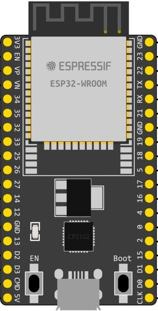
Pin Configuration and Descriptions
The ESP32 Wroom Dev Kit has a variety of pins for different functionalities. Below is a table summarizing the key pins:
| Pin Name | Function | Description |
|---|---|---|
| VIN | Power Input | Accepts 5V input from USB or external power supply. |
| 3V3 | 3.3V Output | Provides 3.3V output for external components. |
| GND | Ground | Common ground for the circuit. |
| EN | Enable | Resets the chip when pulled low. |
| GPIO0 | Boot Mode Selection | Used to enter bootloader mode for programming. |
| GPIO2 | General Purpose I/O | Can be used for digital I/O or special functions. |
| GPIO12-39 | General Purpose I/O | Configurable pins for digital I/O, ADC, DAC, PWM, etc. |
| TXD0, RXD0 | UART0 (Serial Communication) | Default UART pins for serial communication. |
| SCL, SDA | I2C Communication | Used for I2C communication (default GPIO22 and GPIO21). |
| MOSI, MISO, SCK | SPI Communication | Used for SPI communication (default GPIO23, GPIO19, GPIO18). |
| A0-A17 | ADC Channels | Analog input pins with 12-bit resolution. |
| DAC1, DAC2 | Digital-to-Analog Converter | Outputs analog signals (default GPIO25 and GPIO26). |
Note: Pin functionality may vary depending on the board version. Always refer to the specific datasheet for your ESP32 Wroom Dev Kit.
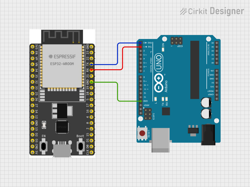
Usage Instructions
How to Use the ESP32 Wroom Dev Kit in a Circuit
Powering the Board:
- Connect the board to your computer via a micro-USB cable for power and programming.
- Alternatively, supply 5V to the VIN pin or 3.3V to the 3V3 pin.
Programming the Board:
- Install the Arduino IDE or ESP-IDF (Espressif IoT Development Framework).
- Add the ESP32 board support package to your IDE.
- Select the correct board and port in the IDE settings.
- Write your code and upload it to the board.
Connecting Peripherals:
- Use the GPIO pins to connect sensors, actuators, or other devices.
- Ensure that the voltage levels of connected devices are compatible with the ESP32 (3.3V logic).
Wi-Fi and Bluetooth Setup:
- Use the built-in libraries (e.g.,
WiFi.handBluetoothSerial.hin Arduino IDE) to configure wireless communication.
- Use the built-in libraries (e.g.,
Important Considerations and Best Practices
- Voltage Levels: The ESP32 operates at 3.3V logic. Avoid connecting 5V signals directly to GPIO pins without level shifting.
- Power Supply: Ensure a stable power supply to avoid unexpected resets or malfunctions.
- Boot Mode: To enter bootloader mode, hold the BOOT button while pressing the EN (reset) button.
- Heat Management: The ESP32 can get warm during operation. Ensure proper ventilation if used in enclosed spaces.
Example Code for Arduino IDE
Below is an example of how to connect the ESP32 Wroom Dev Kit to a Wi-Fi network and blink an LED:
#include <WiFi.h> // Include the Wi-Fi library

// Replace with your network credentials
const char* ssid = "Your_SSID";
const char* password = "Your_PASSWORD";

const int ledPin = 2; // GPIO2 is often connected to the onboard LED

void setup() {
  pinMode(ledPin, OUTPUT); // Set the LED pin as an output
  Serial.begin(115200);    // Start the serial communication

  // Connect to Wi-Fi
  Serial.print("Connecting to Wi-Fi");
  WiFi.begin(ssid, password);
  while (WiFi.status() != WL_CONNECTED) {
    delay(500);
    Serial.print(".");
  }
  Serial.println("\nWi-Fi connected!");
}

void loop() {
  digitalWrite(ledPin, HIGH); // Turn the LED on
  delay(1000);                // Wait for 1 second
  digitalWrite(ledPin, LOW);  // Turn the LED off
  delay(1000);                // Wait for 1 second
}
Troubleshooting and FAQs
Common Issues and Solutions
The board is not detected by the computer:
- Ensure the USB cable is functional and supports data transfer.
- Install the correct USB-to-serial driver for your operating system.
Upload fails with a timeout error:
- Check that the correct board and port are selected in the IDE.
- Hold the BOOT button while uploading the code.
Wi-Fi connection issues:
- Verify the SSID and password.
- Ensure the Wi-Fi network is within range and not using unsupported security protocols.
GPIO pin not working as expected:
- Check if the pin is being used for another function (e.g., ADC, UART).
- Refer to the pinout diagram to confirm the pin's capabilities.
FAQs
Can I power the ESP32 Wroom Dev Kit with a battery?
Yes, you can use a 3.7V LiPo battery connected to the 3V3 pin or a 5V source to the VIN pin.Does the ESP32 support Over-the-Air (OTA) updates?
Yes, the ESP32 supports OTA updates, allowing you to upload new firmware wirelessly.What is the maximum range of the ESP32's Wi-Fi?
The range depends on environmental factors but typically extends up to 100 meters in open spaces.Can I use the ESP32 with MicroPython?
Yes, the ESP32 is compatible with MicroPython, which can be flashed onto the board for Python-based development.