How to Use ATTINY402: Examples, Pinouts, and Specs
Introduction
The ATTINY402 is a low-power 8-bit microcontroller manufactured by Microchip Technology. It is part of the ATtiny family and is designed for compact, energy-efficient applications. With 4KB of Flash memory, 256 bytes of SRAM, and a 12-bit ADC, the ATTINY402 is ideal for small, battery-operated devices. It supports multiple communication protocols, making it versatile for a wide range of embedded systems.
Explore Projects Built with ATTINY402
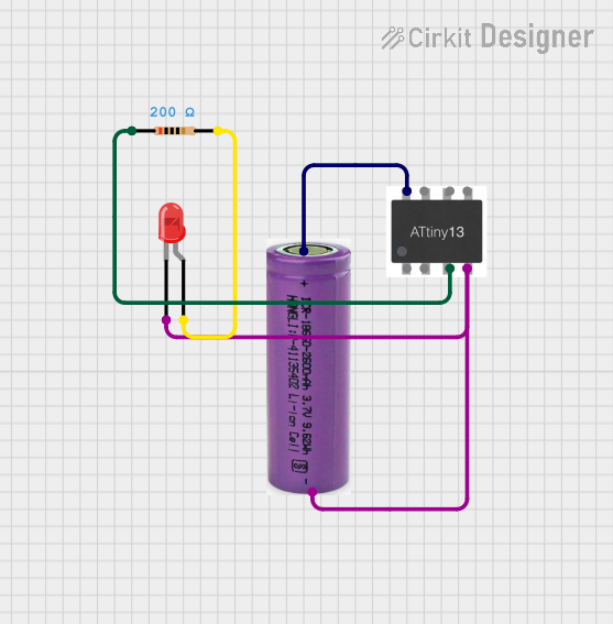
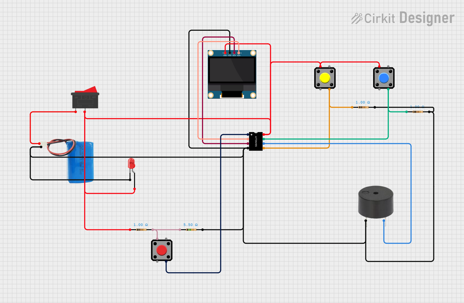


Explore Projects Built with ATTINY402
Common Applications and Use Cases
- Wearable devices
- IoT (Internet of Things) sensors and nodes
- Battery-powered devices
- Home automation systems
- Small-scale robotics
- Consumer electronics
Technical Specifications
Key Technical Details
| Parameter | Value |
|---|---|
| Architecture | 8-bit AVR |
| Flash Memory | 4KB |
| SRAM | 256 bytes |
| EEPROM | 128 bytes |
| Operating Voltage | 1.8V to 5.5V |
| CPU Speed | Up to 20 MHz |
| ADC Resolution | 12-bit |
| Communication Interfaces | USART, SPI, I2C (TWI) |
| GPIO Pins | 11 |
| Power Consumption | Ultra-low power (varies by mode) |
| Package | SOIC, QFN, or DFN |
Pin Configuration and Descriptions
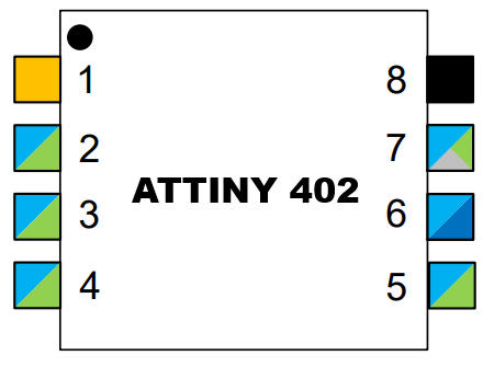
The ATTINY402 is available in an 8-pin package. Below is the pinout and description:
| Pin Number | Pin Name | Description |
|---|---|---|
| 1 | VDD | Power supply (1.8V to 5.5V) |
| 2 | GND | Ground |
| 3 | PA0 | GPIO, ADC input, or alternate function |
| 4 | PA1 | GPIO, ADC input, or alternate function |
| 5 | PA2 | GPIO, ADC input, or alternate function |
| 6 | PA3 | GPIO, ADC input, or alternate function |
| 7 | PA4 | GPIO, ADC input, or alternate function |
| 8 | RESET | Reset pin (active low) |
Usage Instructions
How to Use the ATTINY402 in a Circuit
- Power Supply: Connect the VDD pin to a stable power source (1.8V to 5.5V) and the GND pin to ground.
- Programming: Use an external programmer (e.g., Atmel ICE) to upload firmware via the UPDI (Unified Program and Debug Interface) pin.
- GPIO Configuration: Configure the GPIO pins (PA0 to PA4) as input or output in your firmware, depending on your application.
- Communication: Utilize the USART, SPI, or I2C interfaces for communication with other devices.
- ADC Usage: Use the 12-bit ADC for analog signal measurements by configuring the appropriate pins as ADC inputs.
Important Considerations and Best Practices
- Decoupling Capacitor: Place a 0.1µF ceramic capacitor close to the VDD pin to stabilize the power supply.
- Reset Pin: Ensure the RESET pin is pulled high with a pull-up resistor (e.g., 10kΩ) if not used.
- Low-Power Modes: Take advantage of the ATTINY402's sleep modes to reduce power consumption in battery-operated devices.
- Clock Configuration: Configure the internal oscillator for the desired clock speed (default is 20 MHz).
Example Code for Arduino UNO
Although the ATTINY402 is not directly programmable via Arduino IDE, it can be programmed using the Arduino ecosystem with the appropriate core installed. Below is an example of toggling an LED connected to PA0:
// Include necessary libraries for ATTINY402
#include <avr/io.h>
#include <util/delay.h>

#define LED_PIN 0 // PA0 is pin 0 on ATTINY402

int main(void) {
    // Set PA0 as output
    PORTA.DIR |= (1 << LED_PIN);

    while (1) {
        // Toggle LED
        PORTA.OUT ^= (1 << LED_PIN);
        _delay_ms(500); // Delay for 500ms
    }

    return 0;
}
Note: Ensure you have installed the ATTINY402 core in the Arduino IDE and are using a UPDI programmer for uploading the code.
Troubleshooting and FAQs
Common Issues and Solutions
Microcontroller Not Responding
- Cause: Incorrect power supply or missing decoupling capacitor.
- Solution: Verify the power supply voltage (1.8V to 5.5V) and add a 0.1µF capacitor near the VDD pin.
Programming Failure
- Cause: Incorrect UPDI connection or unsupported programmer.
- Solution: Ensure the UPDI pin is correctly connected to the programmer and use a compatible tool like Atmel ICE.
GPIO Pins Not Functioning
- Cause: Pins not configured correctly in firmware.
- Solution: Double-check the pin configuration in your code and ensure the pins are set as input or output as needed.
High Power Consumption
- Cause: Microcontroller not in low-power mode.
- Solution: Use sleep modes and disable unused peripherals in your firmware.
FAQs
Q: Can the ATTINY402 be programmed using the Arduino IDE?
A: Yes, with the appropriate ATTINY402 core installed and a UPDI programmer, you can program it using the Arduino IDE.
Q: What is the maximum clock speed of the ATTINY402?
A: The ATTINY402 can operate at a maximum clock speed of 20 MHz.
Q: Does the ATTINY402 support external oscillators?
A: No, the ATTINY402 uses an internal oscillator and does not support external oscillators.
Q: How many ADC channels are available?
A: The ATTINY402 has up to 5 ADC channels, depending on the pin configuration.
Q: Can the ATTINY402 operate at 1.8V?
A: Yes, the ATTINY402 supports an operating voltage range of 1.8V to 5.5V.