How to Use Raspberry Pi Camera Module 3 Wide: Examples, Pinouts, and Specs
Introduction
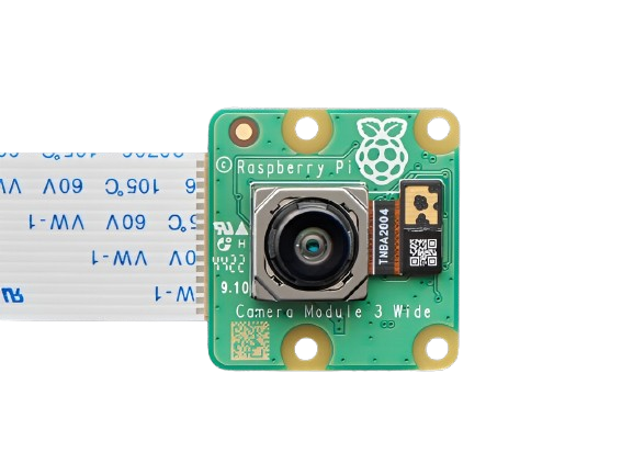
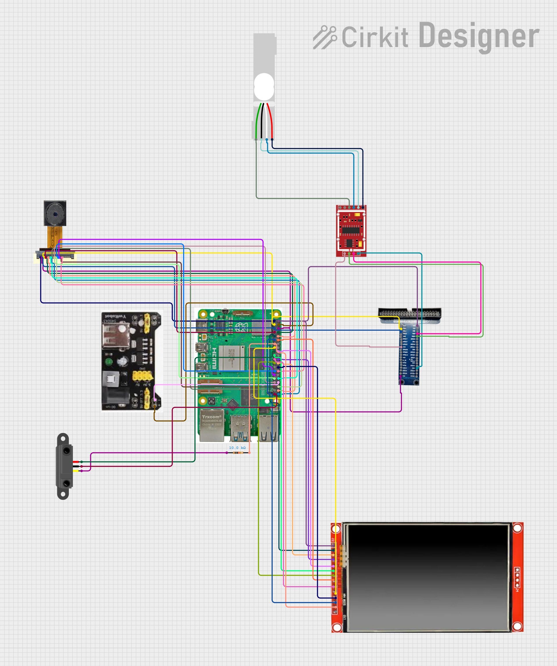
The Raspberry Pi Camera Module 3 Wide is a high-quality camera module designed specifically for Raspberry Pi boards. It features a wide-angle lens, making it ideal for capturing expansive scenes with greater field of view. This module is perfect for applications such as photography, video recording, computer vision, and various imaging projects. Its compact design and compatibility with Raspberry Pi make it a versatile choice for hobbyists, educators, and professionals alike.
Explore Projects Built with Raspberry Pi Camera Module 3 Wide
Explore Projects Built with Raspberry Pi Camera Module 3 Wide
Common Applications and Use Cases
- Photography and videography projects
- Surveillance and security systems
- Machine learning and computer vision applications
- Time-lapse photography
- Robotics and autonomous systems
- Educational projects and prototyping
Technical Specifications
Below are the key technical details of the Raspberry Pi Camera Module 3 Wide:
| Specification | Details |
|---|---|
| Sensor | Sony IMX708 |
| Resolution | 12 Megapixels |
| Lens Type | Wide-angle lens |
| Field of View (FoV) | 120° horizontal |
| Focus Type | Autofocus |
| Video Modes | 1080p at 30fps, 720p at 60fps, 480p at 120fps |
| Interface | CSI-2 (Camera Serial Interface) |
| Dimensions | 25 mm × 24 mm × 11.5 mm |
| Operating Voltage | 3.3V (via Raspberry Pi CSI interface) |
| Operating Temperature | -20°C to 60°C |
| Compatibility | Raspberry Pi boards with a CSI camera connector (e.g., Pi 4, Pi 3, etc.) |
Pin Configuration and Descriptions
The Raspberry Pi Camera Module 3 Wide connects to the Raspberry Pi via the CSI (Camera Serial Interface) port. Below is the pin configuration for the CSI interface:
| Pin Number | Pin Name | Description |
|---|---|---|
| 1 | GND | Ground |
| 2 | 3.3V | Power supply for the camera module |
| 3 | I2C SDA | Serial Data Line for camera control |
| 4 | I2C SCL | Serial Clock Line for camera control |
| 5 | CSI Data Lane 0+ | Positive differential signal for data transmission |
| 6 | CSI Data Lane 0- | Negative differential signal for data transmission |
| 7 | CSI Data Lane 1+ | Positive differential signal for data transmission |
| 8 | CSI Data Lane 1- | Negative differential signal for data transmission |
| 9 | CSI Clock+ | Positive differential signal for clock synchronization |
| 10 | CSI Clock- | Negative differential signal for clock synchronization |
Usage Instructions
How to Use the Camera Module in a Circuit
Connect the Camera Module:
- Locate the CSI port on your Raspberry Pi board.
- Gently lift the plastic clip on the CSI port.
- Insert the ribbon cable from the camera module with the metal contacts facing the Raspberry Pi board.
- Push the plastic clip back down to secure the connection.
Enable the Camera Interface:
- Boot up your Raspberry Pi and open a terminal.
- Run the following command to open the Raspberry Pi configuration tool:
sudo raspi-config - Navigate to
Interface Options>Cameraand enable the camera interface. - Reboot your Raspberry Pi to apply the changes.
Install Required Software:
- Update your Raspberry Pi OS and install the necessary camera libraries:
sudo apt update
sudo apt upgrade
sudo apt install libcamera-apps
- Update your Raspberry Pi OS and install the necessary camera libraries:
Capture Images or Videos:
- Use the
libcameratools to capture images or videos. For example:- Capture an image:
libcamera-still -o image.jpg - Record a video:
(Thelibcamera-vid -o video.h264 -t 10000-toption specifies the duration in milliseconds.)
- Capture an image:
- Use the
Important Considerations and Best Practices
- Ensure the ribbon cable is securely connected to avoid intermittent issues.
- Avoid touching the lens to prevent smudges or scratches.
- Use proper lighting for better image quality.
- If autofocus is not working as expected, ensure the camera module firmware is up to date.
- For long-term projects, consider using a camera case to protect the module.
Example: Using the Camera Module with Arduino UNO
The Raspberry Pi Camera Module 3 Wide is not directly compatible with Arduino UNO due to its reliance on the CSI interface. However, you can use the camera module with a Raspberry Pi and communicate with the Arduino UNO via GPIO pins or serial communication for integrated projects.
Troubleshooting and FAQs
Common Issues and Solutions
Camera Not Detected:
- Ensure the ribbon cable is properly connected to the CSI port.
- Verify that the camera interface is enabled in the Raspberry Pi configuration tool.
- Check for software updates and install the latest camera libraries.
Poor Image Quality:
- Clean the lens with a microfiber cloth to remove smudges.
- Adjust the lighting conditions for better image capture.
- Use the autofocus feature to ensure sharp images.
Autofocus Not Working:
- Ensure the camera module firmware is up to date.
- Test the autofocus by running:
libcamera-still --autofocus
Video Recording Lag:
- Reduce the resolution or frame rate to improve performance.
- Ensure your Raspberry Pi has sufficient power and is not overheating.
FAQs
Q: Can I use the Camera Module 3 Wide with older Raspberry Pi models?
A: The module is compatible with Raspberry Pi boards that have a CSI camera connector. However, performance may vary on older models due to hardware limitations.
Q: What is the maximum resolution supported?
A: The camera supports a maximum resolution of 12 megapixels for still images.
Q: Can I use the camera module for night vision?
A: The Camera Module 3 Wide does not have built-in infrared (IR) capabilities. For night vision, consider using an IR-compatible camera module.
Q: How do I update the camera module firmware?
A: Run the following commands to update the firmware:
sudo apt update
sudo apt upgrade
By following this documentation, you can effectively use the Raspberry Pi Camera Module 3 Wide for a variety of imaging projects.