How to Use Adafruit ST25DV16 I2C RFID EEPROM Breakout: Examples, Pinouts, and Specs
Introduction
The Adafruit ST25DV16 I2C RFID EEPROM Breakout is a versatile and user-friendly component that integrates RFID (Radio-Frequency Identification) capabilities into your electronic projects. It is based on the ST25DV16K chip, which is a dual-interface EEPROM that supports both I2C and NFC (Near Field Communication) interfaces. This breakout board is designed to be easily interfaced with microcontrollers such as Arduino, and it includes an onboard antenna for NFC communication, making it ideal for applications such as contactless data transfer, access control, and asset tracking.
Explore Projects Built with Adafruit ST25DV16 I2C RFID EEPROM Breakout

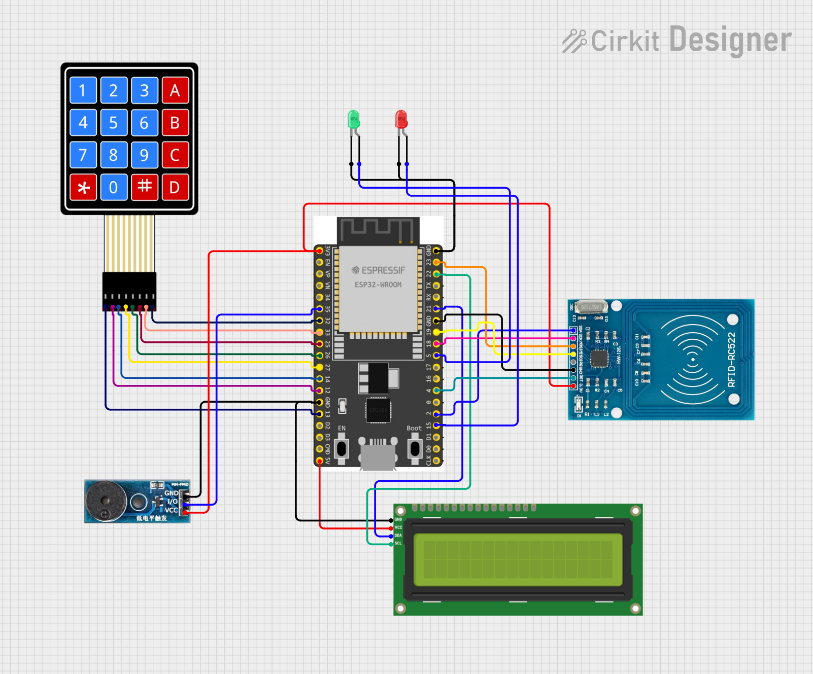
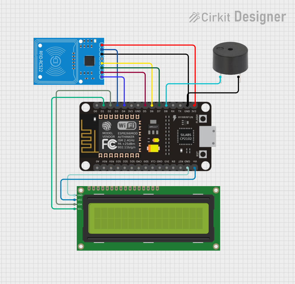
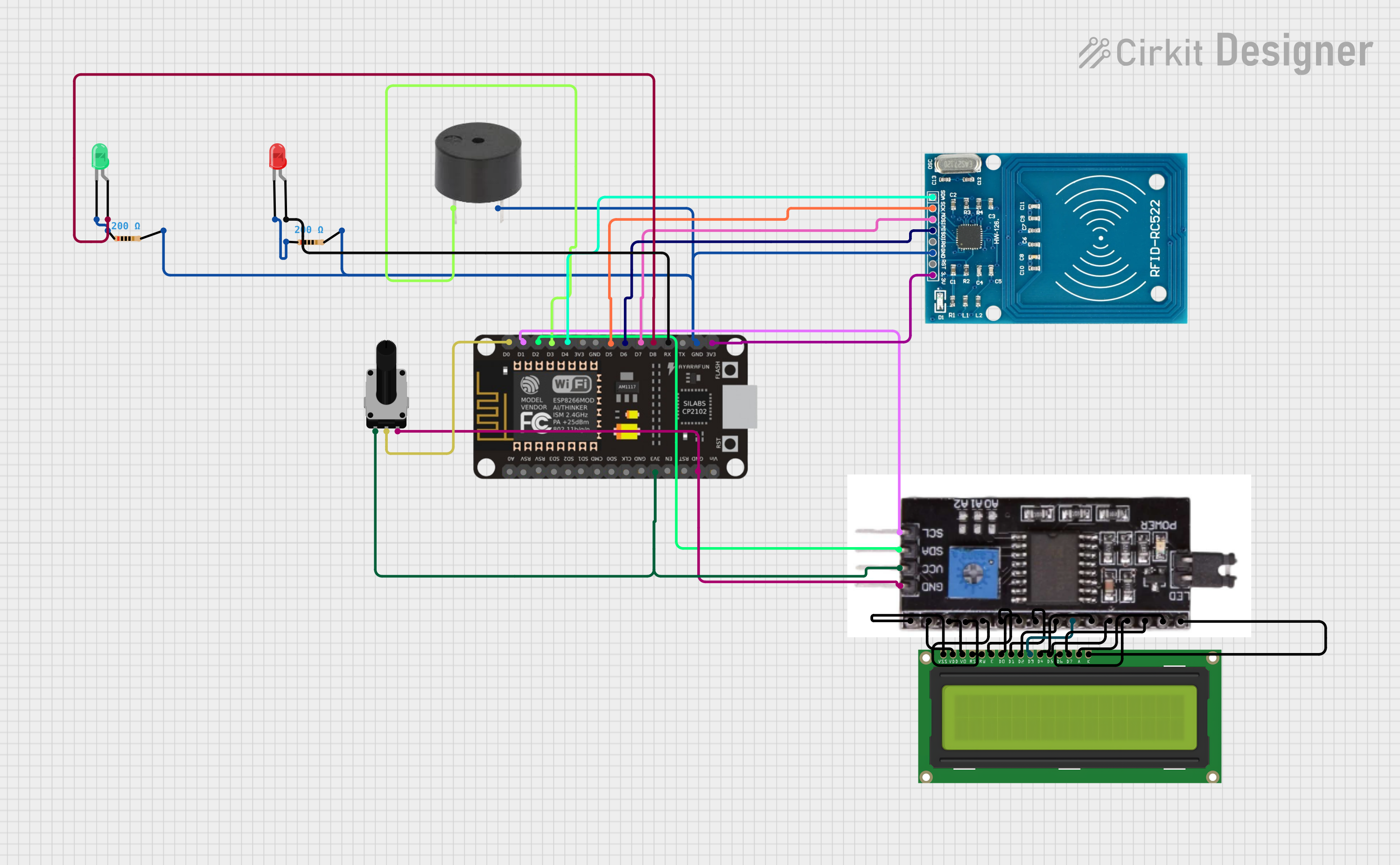
Explore Projects Built with Adafruit ST25DV16 I2C RFID EEPROM Breakout
Common Applications and Use Cases
- Contactless payment systems
- Access control and security systems
- Asset tracking and inventory management
- NFC-enabled smart posters and marketing materials
- Personal identification and consumer electronics
Technical Specifications
Key Technical Details
- Supply Voltage (VCC): 1.8V to 5.5V
- Operating Frequency (NFC): 13.56 MHz
- Memory Size: 16 Kbits of EEPROM
- I2C Interface Speed: Up to 1 Mbit/s
- NFC Communication Range: Up to a few centimeters
- Operating Temperature Range: -40°C to 85°C
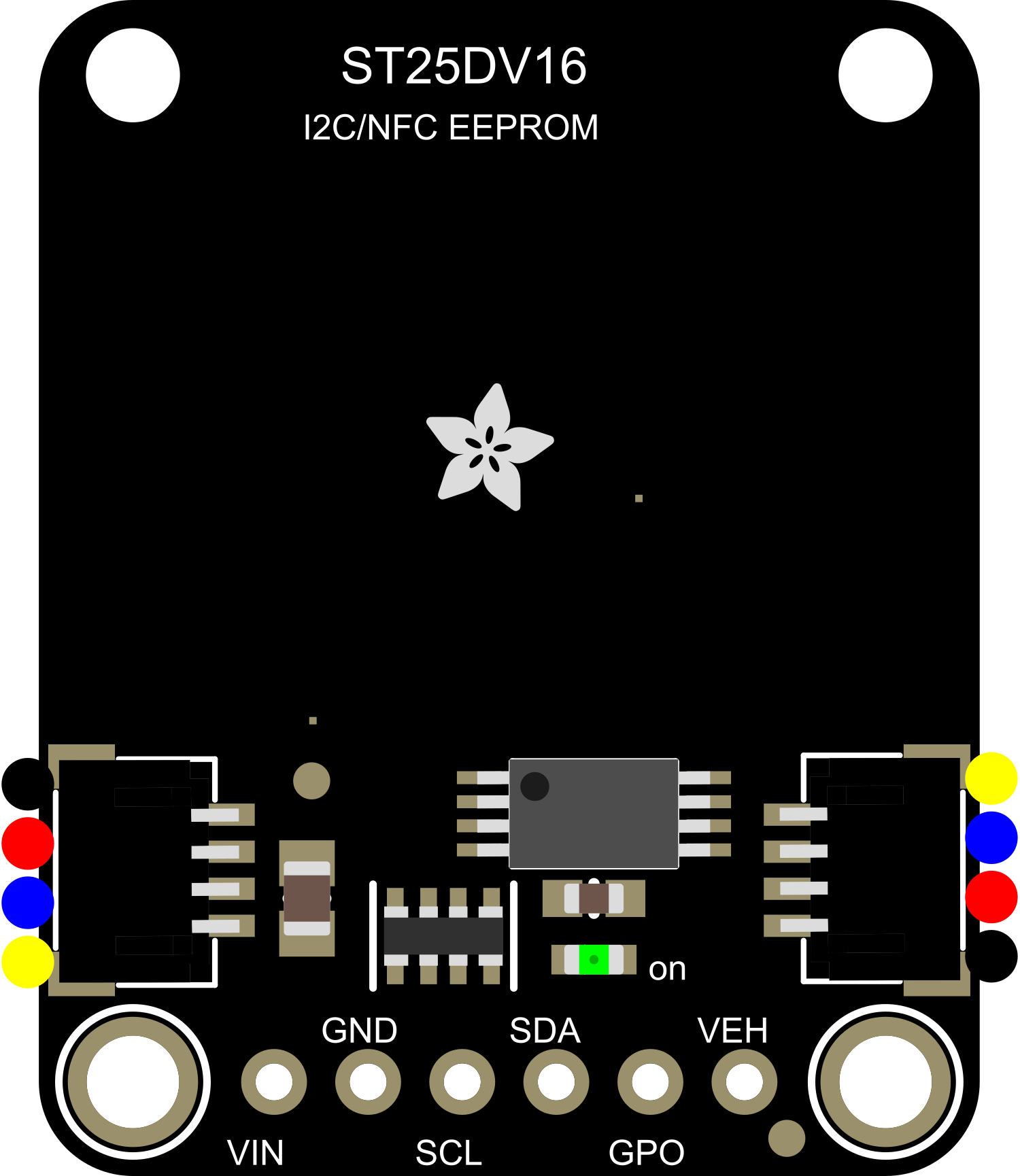
Pin Configuration and Descriptions
| Pin Number | Pin Name | Description |
|---|---|---|
| 1 | VCC | Power supply (1.8V to 5.5V) |
| 2 | GND | Ground |
| 3 | SDA | I2C Data |
| 4 | SCL | I2C Clock |
| 5 | GPO | General Purpose Output (configurable) |
| 6 | RF_DIS | RF Disable (active low) |
| 7 | LED | LED drive (sinks current) |
Usage Instructions
How to Use the Component in a Circuit
Power Connections: Connect the VCC pin to a power supply within the specified range (1.8V to 5.5V) and the GND pin to the ground of your circuit.
I2C Communication: Connect the SDA and SCL pins to the corresponding I2C data and clock lines on your microcontroller. Enable pull-up resistors on these lines if they are not already present on your microcontroller board.
NFC Antenna: The onboard antenna is already connected and ready for NFC communication. Ensure that the breakout board is positioned appropriately for optimal NFC range.
LED Indicator: The LED pin can be connected to an external LED (with a current-limiting resistor) to provide visual feedback for certain operations.
RF Disable: The RF_DIS pin can be used to disable the RF interface when driven low. This can be useful for power-saving modes or when RF functionality is not needed.
General Purpose Output (GPO): The GPO pin can be configured to provide various indications such as RF field detection or EEPROM write cycle completion.
Important Considerations and Best Practices
- Ensure that the power supply voltage does not exceed the maximum rating of 5.5V to prevent damage to the component.
- When using I2C communication, be mindful of the bus speed and address conflicts with other I2C devices.
- For NFC communication, the distance between the breakout board and the NFC reader should be kept to a minimum for reliable data transfer.
- The breakout board should not be subjected to mechanical stress or placed in a conductive environment that could interfere with the NFC antenna.
Troubleshooting and FAQs
Common Issues Users Might Face
- I2C Communication Failure: Check the connections and ensure that the correct I2C address is being used. Also, verify that the pull-up resistors are in place.
- NFC Detection Issues: Ensure that the breakout board is close enough to the NFC reader and that there are no metal objects interfering with the antenna.
- EEPROM Write Errors: Make sure that the power supply is stable and within the specified range. Also, verify that the write protection feature is not enabled inadvertently.
Solutions and Tips for Troubleshooting
- Use a multimeter to check for proper power supply voltage and continuity in the I2C lines.
- If using an Arduino, use the built-in I2C scanner sketch to confirm that the breakout board is detected on the bus.
- For NFC issues, try repositioning the breakout board or testing with a different NFC reader to rule out hardware problems.
FAQs
Q: Can the breakout board be used with any microcontroller? A: Yes, as long as the microcontroller supports I2C communication and operates within the voltage range of the breakout board.
Q: How much data can be stored on the EEPROM? A: The ST25DV16K chip has 16 Kbits (2 KBytes) of EEPROM storage.
Q: Is it possible to write to the EEPROM using NFC? A: Yes, the EEPROM can be written to via both the I2C and NFC interfaces.
Q: What is the maximum range for NFC communication? A: The typical range is a few centimeters, but it can vary depending on the NFC reader and environmental conditions.
Example Arduino Code
Below is an example of how to initialize the Adafruit ST25DV16 I2C RFID EEPROM Breakout with an Arduino UNO:
#include <Wire.h>

// Define the I2C address for the ST25DV16K (check datasheet for the address)
#define ST25DV16K_I2C_ADDRESS 0x53

void setup() {
  Wire.begin(); // Initialize I2C
  Serial.begin(9600); // Start serial communication for debugging

  // Check if the device is connected
  Wire.beginTransmission(ST25DV16K_I2C_ADDRESS);
  if (Wire.endTransmission() == 0) {
    Serial.println("ST25DV16K found!");
  } else {
    Serial.println("ST25DV16K not found, check connections.");
  }
}

void loop() {
  // Your code to interact with the EEPROM goes here
}
Remember to include appropriate error handling and additional functionality as needed for your specific application.