How to Use OLED : Examples, Pinouts, and Specs
Introduction
An Organic Light Emitting Diode (OLED) is a display technology that uses organic compounds to emit light when an electric current is applied. Unlike traditional LCDs, OLEDs do not require a backlight, allowing for thinner, more energy-efficient displays with superior image quality. OLEDs are known for their high contrast ratios, vibrant colors, and ability to produce deep blacks, making them ideal for applications requiring high visual fidelity.
Explore Projects Built with OLED


Explore Projects Built with OLED
Common Applications and Use Cases
- Displays for smartphones, tablets, and televisions
- Wearable devices such as smartwatches
- Industrial and medical equipment displays
- DIY electronics projects and prototyping
- Automotive dashboards and heads-up displays (HUDs)
Technical Specifications
Below are the general technical specifications for a typical small OLED module (e.g., 128x64 resolution):
| Parameter | Specification |
|---|---|
| Display Type | OLED (Organic Light Emitting Diode) |
| Resolution | 128x64 pixels |
| Interface | I2C or SPI |
| Operating Voltage | 3.3V to 5V |
| Operating Current | ~20mA (varies with brightness) |
| Viewing Angle | ~160° |
| Pixel Color | Monochrome (white, blue, or yellow) |
| Dimensions | ~27mm x 27mm x 4mm (varies by model) |
| Operating Temperature | -40°C to 85°C |
Pin Configuration and Descriptions
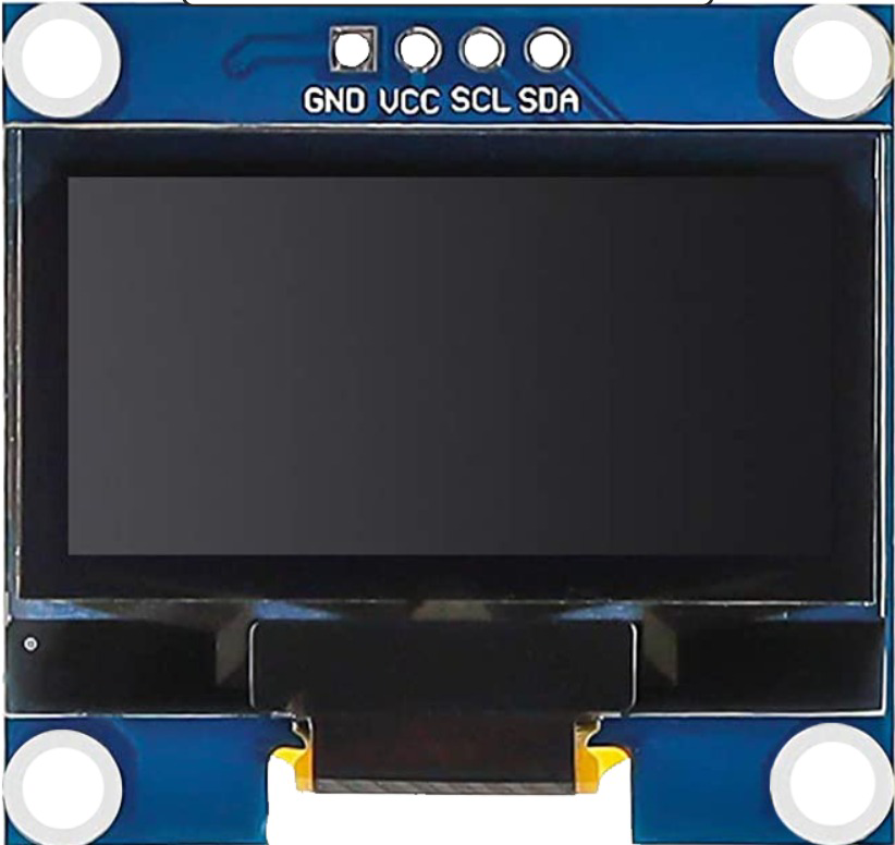
The pinout for a typical 4-pin I2C OLED module is as follows:
| Pin | Name | Description |
|---|---|---|
| 1 | GND | Ground connection |
| 2 | VCC | Power supply (3.3V or 5V) |
| 3 | SCL | Serial Clock Line for I2C communication |
| 4 | SDA | Serial Data Line for I2C communication |
For SPI-based OLED modules, additional pins such as CS (Chip Select) and DC (Data/Command) may be present.
Usage Instructions
How to Use the OLED in a Circuit
- Power Connection: Connect the
VCCpin to a 3.3V or 5V power source and theGNDpin to ground. - Communication Interface:
- For I2C: Connect the
SCLandSDApins to the corresponding I2C pins on your microcontroller. - For SPI: Connect the
CS,DC, and other SPI pins as per the module's datasheet.
- For I2C: Connect the
- Pull-Up Resistors: If using I2C, ensure pull-up resistors (typically 4.7kΩ) are present on the
SCLandSDAlines. - Software Library: Use a compatible library (e.g., Adafruit SSD1306 or U8g2) to control the OLED.
Important Considerations and Best Practices
- Voltage Compatibility: Ensure the OLED module's voltage matches your microcontroller's logic level (3.3V or 5V).
- Brightness Control: Prolong the OLED's lifespan by reducing brightness when possible.
- Initialization: Always initialize the OLED using the appropriate commands or library functions before displaying data.
- Avoid Burn-In: Prevent static images from being displayed for extended periods to avoid burn-in.
Example Code for Arduino UNO
Below is an example of using an I2C OLED module with an Arduino UNO and the Adafruit SSD1306 library:
#include <Wire.h>
#include <Adafruit_GFX.h>
#include <Adafruit_SSD1306.h>

// Define OLED display dimensions
#define SCREEN_WIDTH 128
#define SCREEN_HEIGHT 64

// Create an SSD1306 display object (I2C address 0x3C is common for OLEDs)
Adafruit_SSD1306 display(SCREEN_WIDTH, SCREEN_HEIGHT, &Wire, -1);

void setup() {
  // Initialize serial communication for debugging
  Serial.begin(9600);

  // Initialize the OLED display
  if (!display.begin(SSD1306_I2C_ADDRESS, 0x3C)) {
    Serial.println(F("SSD1306 allocation failed"));
    for (;;); // Halt execution if initialization fails
  }

  // Clear the display buffer
  display.clearDisplay();

  // Display a welcome message
  display.setTextSize(1); // Set text size
  display.setTextColor(SSD1306_WHITE); // Set text color
  display.setCursor(0, 0); // Set cursor position
  display.println(F("Hello, OLED!")); // Print message
  display.display(); // Update the display
  delay(2000); // Pause for 2 seconds
}

void loop() {
  // Example: Draw a rectangle on the OLED
  display.clearDisplay(); // Clear the display buffer
  display.drawRect(10, 10, 50, 30, SSD1306_WHITE); // Draw a rectangle
  display.display(); // Update the display
  delay(1000); // Pause for 1 second
}
Troubleshooting and FAQs
Common Issues and Solutions
OLED Not Powering On:
- Verify the
VCCandGNDconnections. - Ensure the power supply voltage matches the OLED module's requirements.
- Verify the
No Display Output:
- Check the I2C or SPI connections and ensure they are correctly wired.
- Confirm the I2C address (default is often
0x3Cor0x3D) matches the library settings. - Ensure the OLED is initialized properly in the code.
Flickering or Artifacts:
- Check for loose connections or poor solder joints.
- Reduce the I2C clock speed if communication issues persist.
Burn-In or Image Retention:
- Avoid displaying static images for long periods.
- Use screen savers or periodically refresh the display content.
FAQs
Q: Can I use the OLED with a 3.3V microcontroller?
A: Yes, most OLED modules are compatible with both 3.3V and 5V logic levels. Check the datasheet to confirm.
Q: What is the maximum cable length for I2C communication?
A: I2C is designed for short distances (typically less than 1 meter). For longer distances, consider using SPI or additional hardware like I2C extenders.
Q: How do I change the I2C address of my OLED module?
A: Some OLED modules allow changing the I2C address by soldering jumpers on the back of the module. Refer to the module's datasheet for details.
Q: Can I use multiple OLEDs on the same I2C bus?
A: Yes, but each OLED must have a unique I2C address. Use modules with configurable addresses or an I2C multiplexer.
By following this documentation, you can effectively integrate and troubleshoot OLED modules in your projects.