How to Use Adafruit ADS1115 16Bit I2C ADC: Examples, Pinouts, and Specs
Introduction
The Adafruit ADS1115 is a high-precision, 16-bit Analog-to-Digital Converter (ADC) that operates on an I2C bus interface. It is designed to accurately convert analog signals to digital form, allowing microcontrollers and other digital systems to process real-world data such as temperature, pressure, or light intensity. The ADS1115 is particularly useful in applications requiring high-resolution measurements, such as data loggers, sensors, and precision instrumentation.
Explore Projects Built with Adafruit ADS1115 16Bit I2C ADC


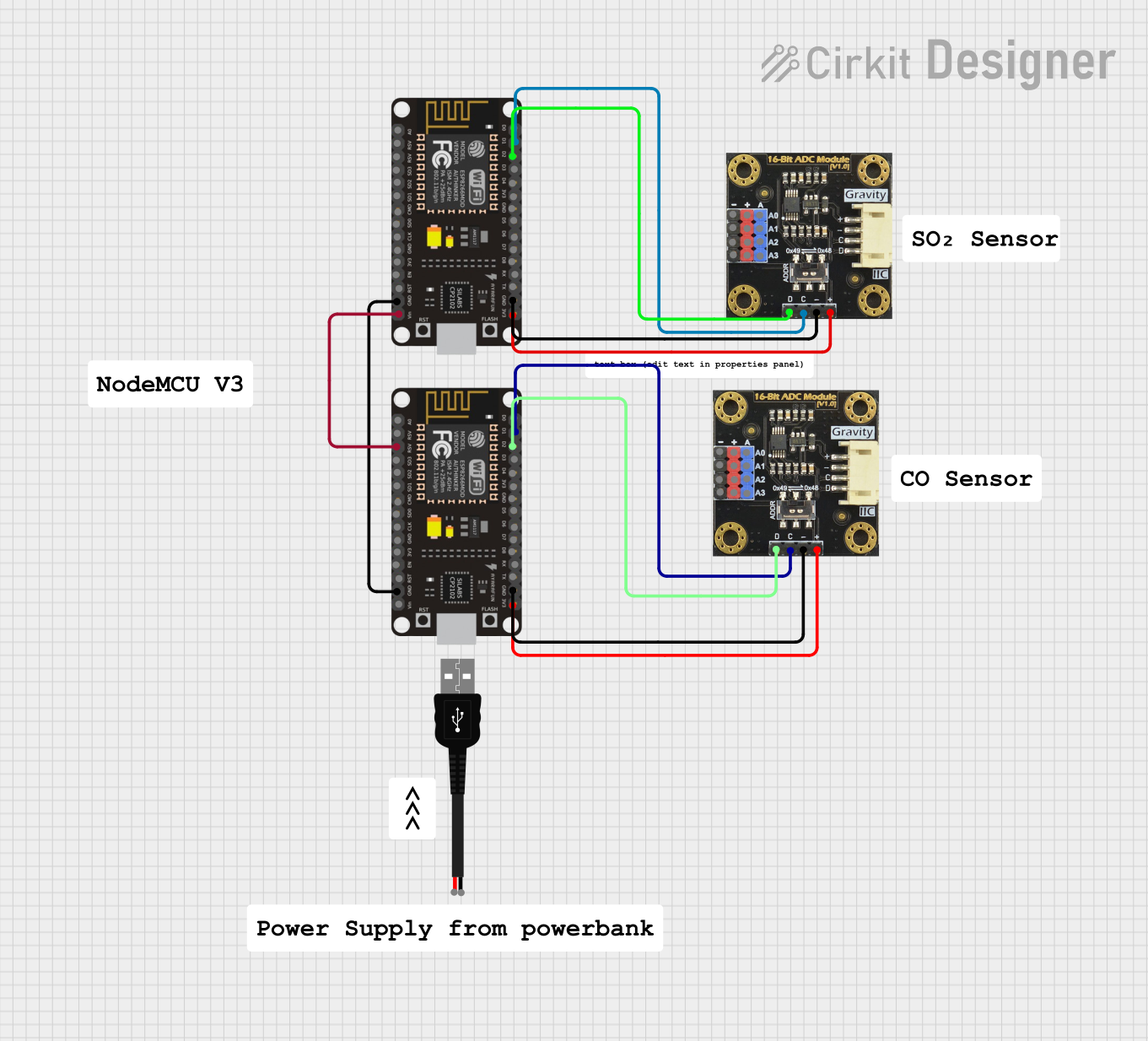
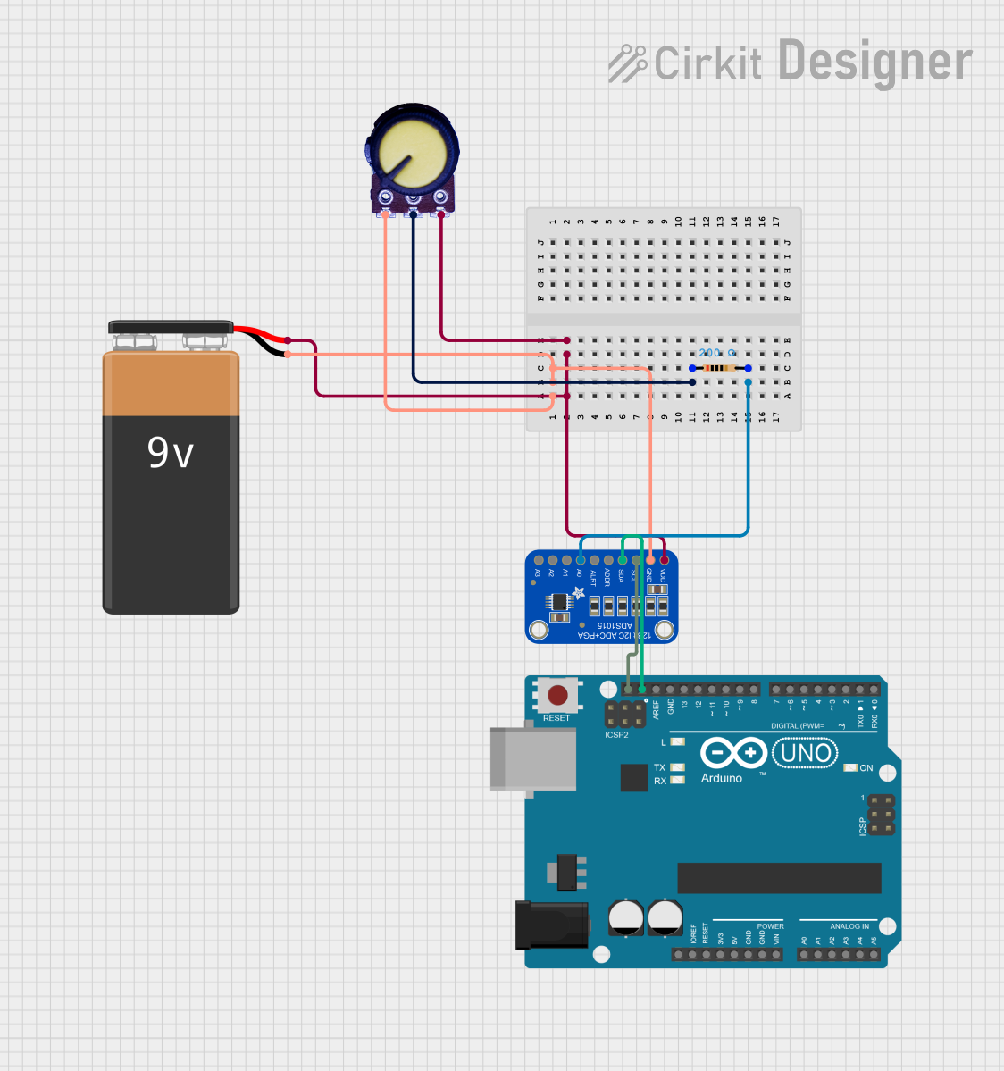
Explore Projects Built with Adafruit ADS1115 16Bit I2C ADC
Technical Specifications
Key Features
- Resolution: 16-bit
- Sampling Rate: Up to 860 samples per second (SPS)
- Input Channels: 4 single-ended or 2 differential
- Programmable Gain Amplifier (PGA): Up to ±6.144V
- Supply Voltage: 2.0V to 5.5V
- Interface: I2C
- I2C Addresses: 0x48 (default), 0x49, 0x4A, 0x4B (selectable with address pin)
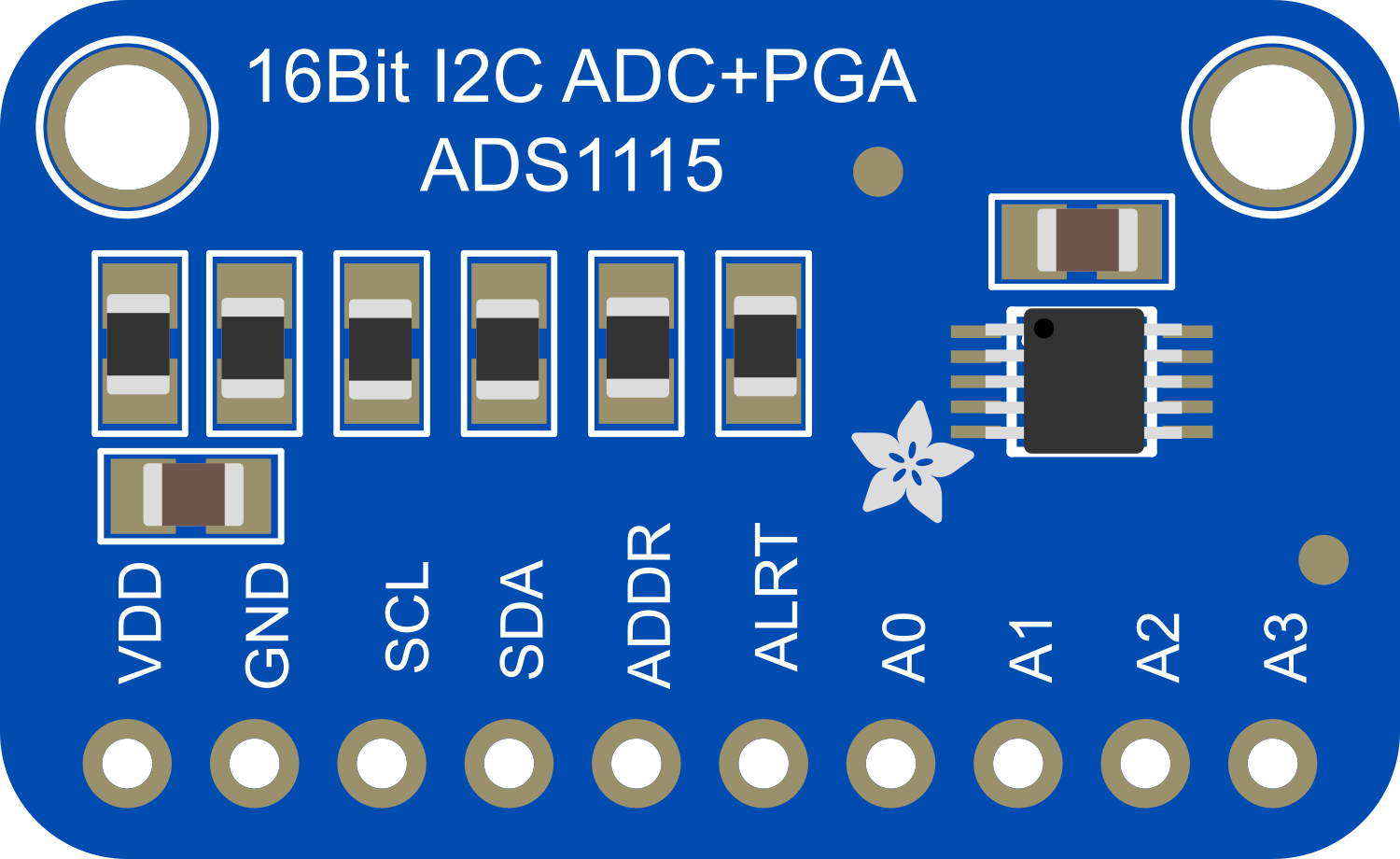
Pin Configuration
| Pin Number | Pin Name | Description |
|---|---|---|
| 1 | VDD | Power supply (2.0V to 5.5V) |
| 2 | GND | Ground |
| 3 | SCL | I2C clock |
| 4 | SDA | I2C data |
| 5 | ADDR | Address selection pin |
| 6 | ALERT | Alert/Ready pin (optional use) |
| 7 | A0 | Analog input channel 0 |
| 8 | A1 | Analog input channel 1 |
| 9 | A2 | Analog input channel 2 |
| 10 | A3 | Analog input channel 3 |
Usage Instructions
Connecting to a Circuit
- Power Connections: Connect VDD to a 2.0V to 5.5V power supply and GND to the system ground.
- I2C Connections: Connect SCL and SDA to the corresponding I2C clock and data lines on your microcontroller. Use pull-up resistors as required by your I2C bus specifications.
- Address Selection: Connect the ADDR pin to GND, VDD, SDA, or SCL to select one of the four possible I2C addresses.
- Analog Inputs: Connect your analog signal to any of the A0 to A3 pins. For differential measurements, use pairs A0/A1 or A2/A3.
Programming with Arduino
To use the ADS1115 with an Arduino, you can utilize the Adafruit ADS1X15 library. Here's a basic example of how to read a single-ended voltage from channel A0:
#include <Wire.h>
#include <Adafruit_ADS1015.h>

Adafruit_ADS1115 ads;  // Create an instance of the ADS1115

void setup() {
  Serial.begin(9600);
  ads.begin();  // Initialize the ADS1115
}

void loop() {
  int16_t adc0;  // Variable to hold the ADC result

  adc0 = ads.readADC_SingleEnded(0);  // Read from channel 0
  Serial.print("AIN0: "); Serial.println(adc0);
  delay(1000);  // Wait for a second
}
Best Practices
- Ensure that the input voltage does not exceed the selected full-scale range of the PGA.
- Use decoupling capacitors close to the power pins to minimize noise.
- Keep analog signal paths as short as possible to reduce noise pickup.
- Avoid running analog signal lines parallel to high-current traces to prevent interference.
Troubleshooting and FAQs
Common Issues
- No response from the device: Check the I2C connections, ensure pull-up resistors are installed, and verify that the correct I2C address is being used.
- Inaccurate readings: Ensure that the input voltage is within the range set by the PGA. Check for noise in the analog signal and power supply lines.
FAQs
Q: Can the ADS1115 be used with a 3.3V system? A: Yes, the ADS1115 can operate at voltages as low as 2.0V.
Q: How do I change the I2C address of the ADS1115? A: The I2C address can be changed by connecting the ADDR pin to GND, VDD, SDA, or SCL.
Q: What is the maximum voltage that can be measured by the ADS1115? A: The maximum voltage is determined by the PGA setting, which can be up to ±6.144V.
Q: How can I use the ALERT pin? A: The ALERT pin can be configured for various functions such as a conversion ready signal or a threshold alert. Refer to the ADS1115 datasheet for detailed configuration options.
For further assistance, consult the ADS1115 datasheet and the Adafruit ADS1X15 library documentation.