
How to Use ADXL375: Examples, Pinouts, and Specs
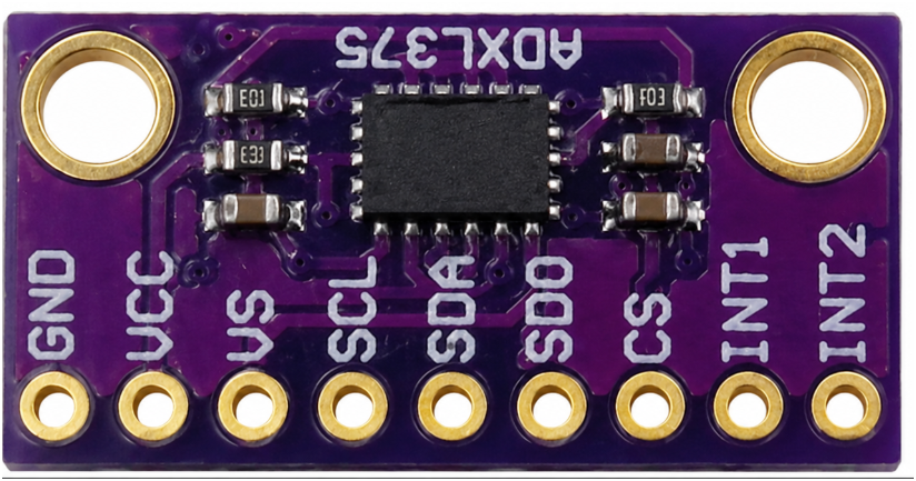
 Design with ADXL375 in Cirkit Designer
Introduction
The ADXL375 is a low-power, 3-axis accelerometer with a digital output, designed for motion sensing applications. It features a wide measurement range of ±200 g, high resolution, and built-in digital filtering capabilities. This makes it ideal for applications requiring precise motion detection, such as industrial vibration monitoring, impact detection, and sports equipment analysis.
Explore Projects Built with ADXL375
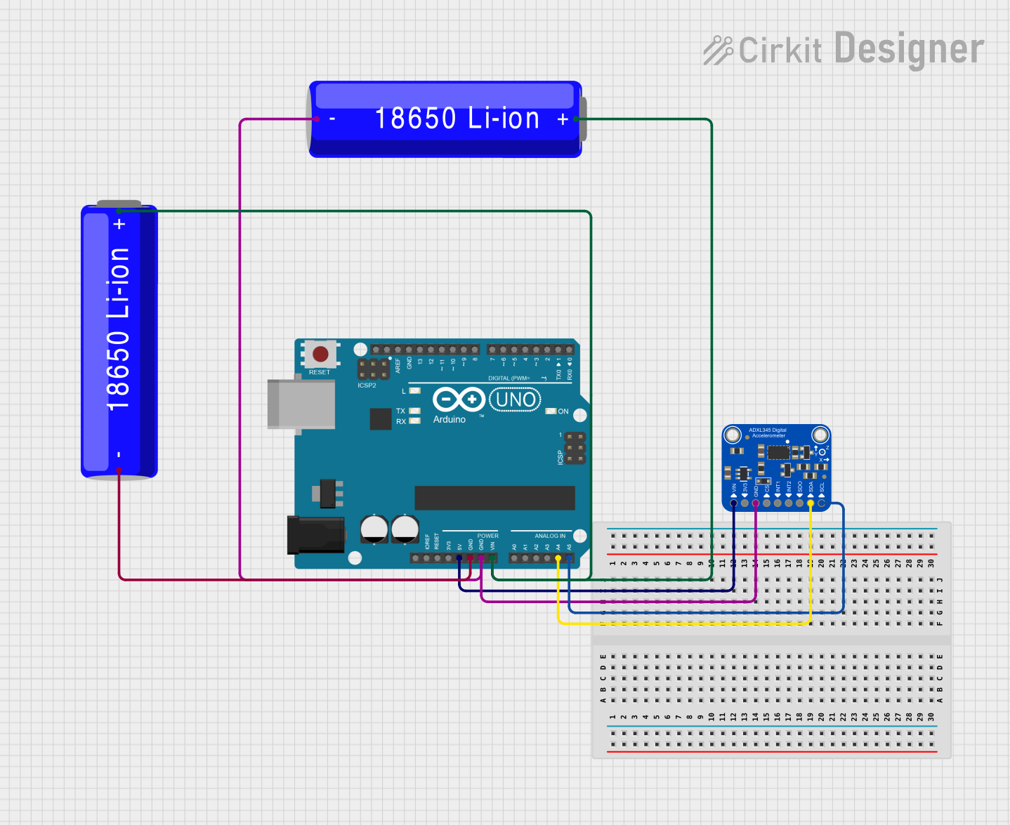 Open Project in Cirkit Designer
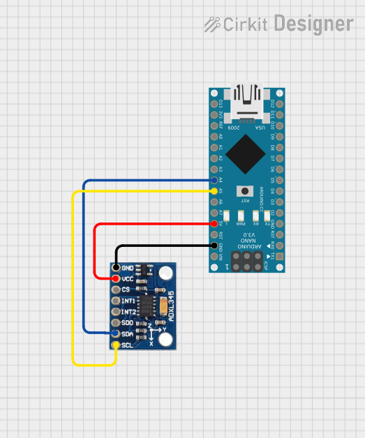 Open Project in Cirkit Designer
 Open Project in Cirkit Designer
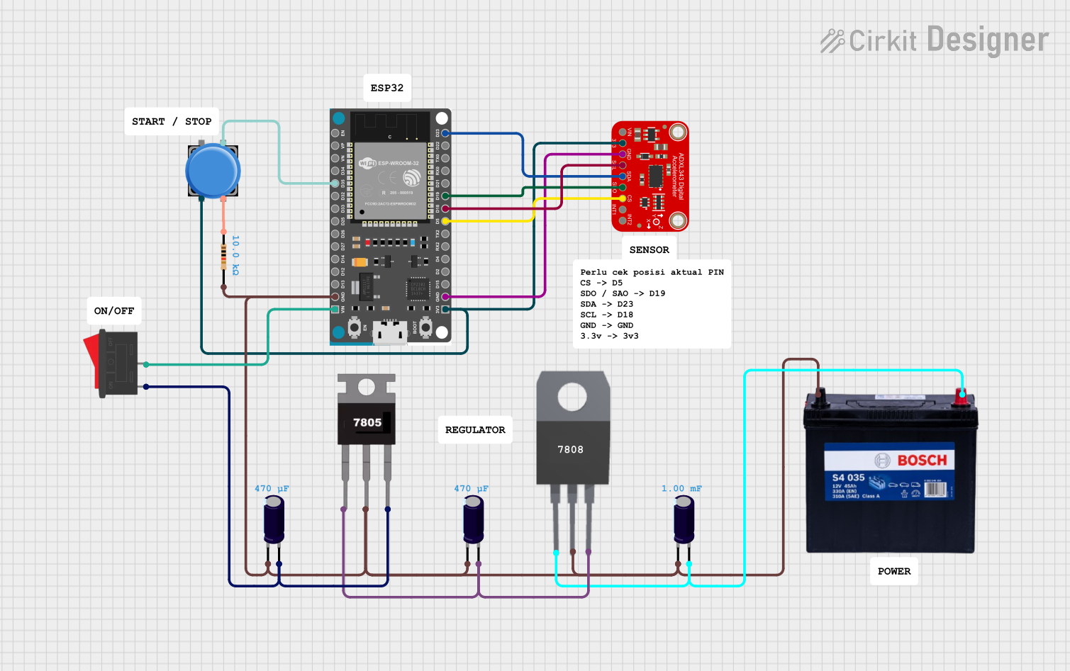 Open Project in Cirkit Designer
Explore Projects Built with ADXL375
Open Project in Cirkit DesignerOpen Project in Cirkit DesignerOpen Project in Cirkit DesignerOpen Project in Cirkit DesignerCommon Applications
- Impact and shock detection
- Industrial equipment monitoring
- Sports and fitness devices
- Automotive crash testing
- Structural health monitoring
Technical Specifications
Key Specifications
| Parameter | Value |
|---|---|
| Measurement Range | ±200 g |
| Supply Voltage (VDD) | 2.0 V to 3.6 V |
| Output Type | Digital (SPI/I²C) |
| Resolution | 13-bit |
| Power Consumption | 140 µA (typical) at 2.5 V |
| Operating Temperature Range | -40°C to +85°C |
| Bandwidth | Configurable up to 1600 Hz |
| Shock Survivability | 10,000 g |
Pin Configuration
The ADXL375 is typically available in a 14-pin LGA package. Below is the pinout description:
| Pin Number | Pin Name | Description |
|---|---|---|
| 1 | VDD | Power supply (2.0 V to 3.6 V) |
| 2 | GND | Ground |
| 3 | CS | Chip Select (Active Low) for SPI communication |
| 4 | SDO/ALT | SPI Data Out or Alternate I²C Address Select |
| 5 | SDA/SDI | I²C Data or SPI Data In |
| 6 | SCL/SCLK | I²C Clock or SPI Clock |
| 7-14 | NC | No Connection (leave unconnected) |
Usage Instructions
Using the ADXL375 in a Circuit
- Power Supply: Connect the VDD pin to a 2.0 V to 3.6 V power source and the GND pin to ground.
- Communication Interface: Choose between SPI or I²C communication:
- For SPI, connect the CS, SDO, SDA, and SCL pins to the corresponding SPI pins on your microcontroller.
- For I²C, connect the SDA and SCL pins to the I²C bus, and use a pull-up resistor (typically 4.7 kΩ) on each line.
- Configuration: Configure the ADXL375's registers to set the desired measurement range, bandwidth, and output data rate.
- Data Reading: Continuously read acceleration data from the X, Y, and Z axes via the selected communication interface.
Important Considerations
- Bypass Capacitor: Place a 0.1 µF ceramic capacitor close to the VDD pin to reduce noise.
- Mounting: Ensure the ADXL375 is securely mounted to minimize mechanical noise and improve measurement accuracy.
- Interrupts: Use the built-in interrupt pins for event detection, such as free-fall or impact events.
Example Code for Arduino UNO (I²C Communication)
#include <Wire.h>

// ADXL375 I²C address (default: 0x53)
#define ADXL375_ADDRESS 0x53

// Register addresses
#define POWER_CTL 0x2D
#define DATA_FORMAT 0x31
#define DATAX0 0x32

void setup() {
  Wire.begin(); // Initialize I²C communication
  Serial.begin(9600); // Initialize serial communication for debugging

  // Initialize ADXL375
  Wire.beginTransmission(ADXL375_ADDRESS);
  Wire.write(POWER_CTL); // Select Power Control register
  Wire.write(0x08); // Set measurement mode
  Wire.endTransmission();

  Wire.beginTransmission(ADXL375_ADDRESS);
  Wire.write(DATA_FORMAT); // Select Data Format register
  Wire.write(0x0B); // Set full resolution and ±200 g range
  Wire.endTransmission();
}

void loop() {
  int16_t x, y, z;

  // Request data from ADXL375
  Wire.beginTransmission(ADXL375_ADDRESS);
  Wire.write(DATAX0); // Start reading from DATAX0 register
  Wire.endTransmission(false);
  Wire.requestFrom(ADXL375_ADDRESS, 6); // Read 6 bytes (X, Y, Z)

  if (Wire.available() == 6) {
    x = (Wire.read() | (Wire.read() << 8)); // Combine low and high bytes for X
    y = (Wire.read() | (Wire.read() << 8)); // Combine low and high bytes for Y
    z = (Wire.read() | (Wire.read() << 8)); // Combine low and high bytes for Z
  }

  // Print acceleration values
  Serial.print("X: "); Serial.print(x);
  Serial.print(" Y: "); Serial.print(y);
  Serial.print(" Z: "); Serial.println(z);

  delay(100); // Delay for readability
}
Troubleshooting and FAQs
Common Issues
No Data Output:
- Ensure the ADXL375 is powered correctly (check VDD and GND connections).
- Verify that the communication interface (SPI/I²C) is configured properly.
- Check the register configuration, especially the
POWER_CTLregister.
Incorrect Acceleration Values:
- Confirm that the data format and measurement range are set correctly.
- Ensure the device is mounted securely to avoid mechanical noise.
I²C Communication Failure:
- Check the pull-up resistors on the SDA and SCL lines.
- Verify the I²C address (default is 0x53, but it may change if the ALT pin is used).
Tips for Troubleshooting
- Use an oscilloscope or logic analyzer to monitor the communication lines.
- Refer to the ADXL375 datasheet for detailed register descriptions and configuration options.
- Test the accelerometer with a simple script to verify basic functionality before integrating it into a larger project.
FAQs
Q: Can the ADXL375 detect free-fall events?
A: Yes, the ADXL375 has built-in free-fall detection, which can be configured using its interrupt registers.
Q: What is the maximum sampling rate of the ADXL375?
A: The ADXL375 supports a maximum output data rate of 3200 Hz, but the bandwidth is limited to 1600 Hz.
Q: Can I use the ADXL375 with a 5V microcontroller?
A: Yes, but you will need a level shifter to interface the 3.3V logic of the ADXL375 with the 5V logic of the microcontroller.