Cirkit Designer Logo
Cirkit Designer
Your all-in-one circuit design IDE
Home / 
Component Documentation

How to Use Adafruit 2.7in 400x240 SHARP Memory Display: Examples, Pinouts, and Specs

Image of Adafruit 2.7in 400x240 SHARP Memory Display
Cirkit Designer LogoDesign with Adafruit 2.7in 400x240 SHARP Memory Display in Cirkit Designer

Introduction

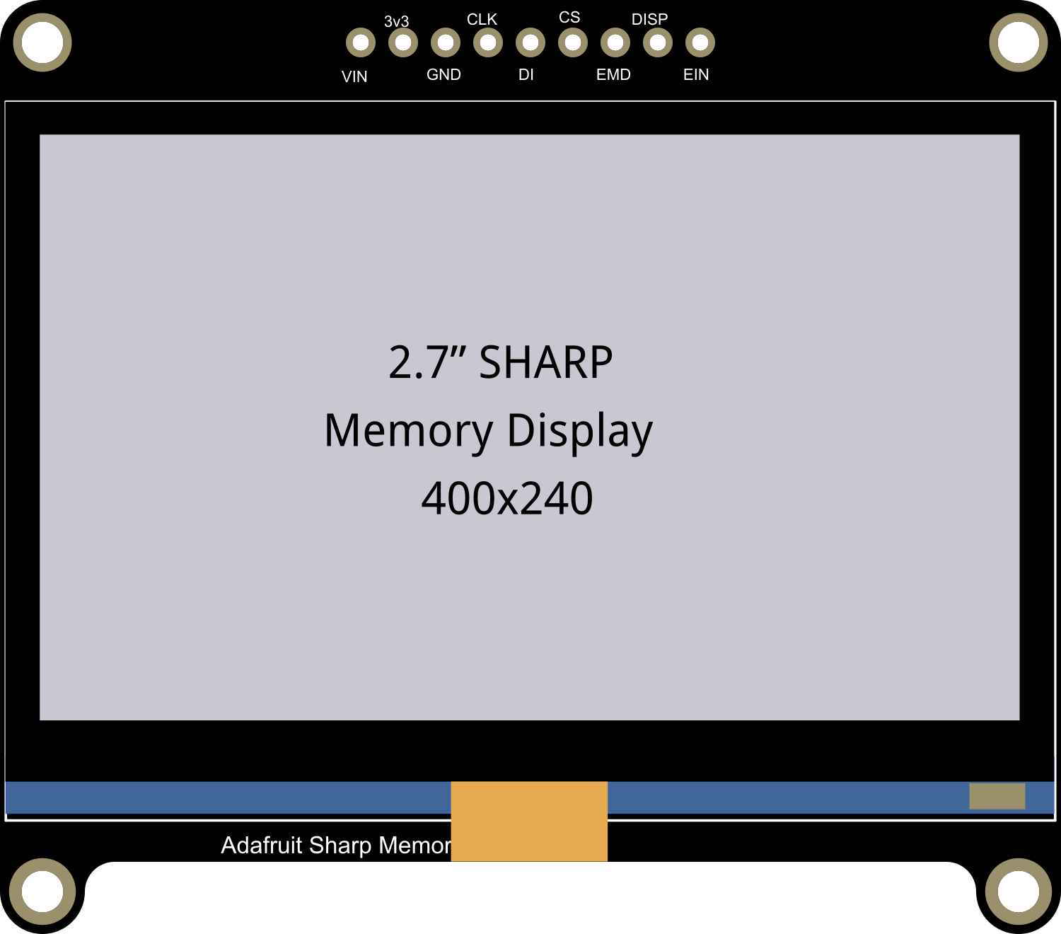
The Adafruit 2.7in 400x240 SHARP Memory Display is a sophisticated electronic component that offers a crisp and detailed visual output on a 2.7-inch color LCD screen. With a resolution of 400x240 pixels, this display module is capable of presenting intricate graphics and legible text, making it an ideal choice for a wide range of applications that demand high-quality visual representation. The integrated memory controller simplifies the process of interfacing with various microcontrollers, including popular platforms like Arduino UNO.

Explore Projects Built with Adafruit 2.7in 400x240 SHARP Memory Display

Use Cirkit Designer to design, explore, and prototype these projects online. Some projects support real-time simulation. Click "Open Project" to start designing instantly!
Arduino Mega 2560 Controlled TFT Touchscreen Interface
Image of Tablero Moto: A project utilizing Adafruit 2.7in 400x240 SHARP Memory Display in a practical application
This circuit connects an Arduino Mega 2560 microcontroller to a 3.5-inch 480x320 TFT LCD display. The Arduino provides power, ground, and digital signals to control the display, including data lines for pixel information and control lines for reset, write, and command/data selection. The embedded code initializes the display and configures the Arduino's pins for communication, likely to create a user interface or visual output for a project.
Cirkit Designer LogoOpen Project in Cirkit Designer
Arduino Nano and OLED Display for Real-Time Data Visualization
Image of OLED Display: A project utilizing Adafruit 2.7in 400x240 SHARP Memory Display in a practical application
This circuit consists of an Arduino Nano microcontroller connected to a 0.96" OLED display. The Arduino Nano provides power to the OLED display and communicates with it using the I2C protocol via the A4 (SDA) and A5 (SCK) pins.
Cirkit Designer LogoOpen Project in Cirkit Designer
Arduino 101 OLED Display Animation Project
Image of wokwi animater test: A project utilizing Adafruit 2.7in 400x240 SHARP Memory Display in a practical application
This circuit consists of an Arduino 101 microcontroller connected to a 0.96" OLED display via I2C communication. The Arduino runs a program that initializes the OLED and continuously displays an animated sequence of frames on the screen.
Cirkit Designer LogoOpen Project in Cirkit Designer
Arduino UNO-Based OLED Display with Dual Pushbutton Control
Image of pong game: A project utilizing Adafruit 2.7in 400x240 SHARP Memory Display in a practical application
This circuit features an Arduino UNO microcontroller interfaced with a 0.96" OLED display and two pushbuttons. The OLED display is connected to the Arduino via the I2C protocol (SCK to A5 and SDA to A4), while the pushbuttons are connected to digital pins D2 and D3 for user input. The setup is likely intended for a simple interactive display application.
Cirkit Designer LogoOpen Project in Cirkit Designer

Explore Projects Built with Adafruit 2.7in 400x240 SHARP Memory Display

Use Cirkit Designer to design, explore, and prototype these projects online. Some projects support real-time simulation. Click "Open Project" to start designing instantly!
Image of Tablero Moto: A project utilizing Adafruit 2.7in 400x240 SHARP Memory Display in a practical application
Arduino Mega 2560 Controlled TFT Touchscreen Interface
This circuit connects an Arduino Mega 2560 microcontroller to a 3.5-inch 480x320 TFT LCD display. The Arduino provides power, ground, and digital signals to control the display, including data lines for pixel information and control lines for reset, write, and command/data selection. The embedded code initializes the display and configures the Arduino's pins for communication, likely to create a user interface or visual output for a project.
Cirkit Designer LogoOpen Project in Cirkit Designer
Image of OLED Display: A project utilizing Adafruit 2.7in 400x240 SHARP Memory Display in a practical application
Arduino Nano and OLED Display for Real-Time Data Visualization
This circuit consists of an Arduino Nano microcontroller connected to a 0.96" OLED display. The Arduino Nano provides power to the OLED display and communicates with it using the I2C protocol via the A4 (SDA) and A5 (SCK) pins.
Cirkit Designer LogoOpen Project in Cirkit Designer
Image of wokwi animater test: A project utilizing Adafruit 2.7in 400x240 SHARP Memory Display in a practical application
Arduino 101 OLED Display Animation Project
This circuit consists of an Arduino 101 microcontroller connected to a 0.96" OLED display via I2C communication. The Arduino runs a program that initializes the OLED and continuously displays an animated sequence of frames on the screen.
Cirkit Designer LogoOpen Project in Cirkit Designer
Image of pong game: A project utilizing Adafruit 2.7in 400x240 SHARP Memory Display in a practical application
Arduino UNO-Based OLED Display with Dual Pushbutton Control
This circuit features an Arduino UNO microcontroller interfaced with a 0.96" OLED display and two pushbuttons. The OLED display is connected to the Arduino via the I2C protocol (SCK to A5 and SDA to A4), while the pushbuttons are connected to digital pins D2 and D3 for user input. The setup is likely intended for a simple interactive display application.
Cirkit Designer LogoOpen Project in Cirkit Designer

Common Applications and Use Cases

  • Portable instruments and diagnostic devices
  • User interfaces for embedded systems
  • Wearable technology
  • Custom gaming devices
  • Educational electronics projects

Technical Specifications

Key Technical Details

  • Display Type: LCD
  • Screen Size: 2.7 inches
  • Resolution: 400x240 pixels
  • Interface: SPI
  • Operating Voltage: 3.3V
  • Current Consumption: Typically 10 mA (depends on the update rate and usage)

Pin Configuration and Descriptions

Pin Number Name Description
1 GND Ground connection
2 VCC Power supply (3.3V)
3 SCLK Serial Clock for SPI
4 MOSI Master Out Slave In for SPI
5 CS Chip Select
6 EXTMODE External Mode Select
7 DISP Display On/Off control
8 VCOM Serial Clock for VCOM switching

Usage Instructions

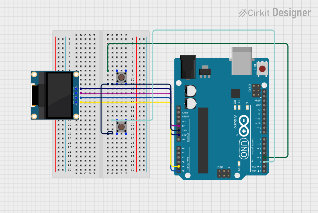
Interfacing with a Circuit

  1. Power Connections: Connect the VCC pin to a 3.3V power supply and the GND pin to the ground.
  2. SPI Interface: Connect the SCLK and MOSI pins to the corresponding SPI pins on your microcontroller.
  3. Control Pins: Connect the CS, EXTMODE, DISP, and VCOM pins to available digital I/O pins on your microcontroller.

Important Considerations and Best Practices

  • Ensure that the power supply is 3.3V; higher voltages may damage the display.
  • Use a level shifter if interfacing with a 5V microcontroller like the Arduino UNO.
  • Keep the SPI clock speed within the display's maximum rating.
  • Avoid static discharge by grounding yourself before handling the display.
  • When updating the display frequently, manage power consumption and heat dissipation.

Example Code for Arduino UNO

#include <SPI.h>
#include <Adafruit_SharpMem.h>

// Display connection pins
#define SHARP_SCK  13
#define SHARP_MOSI 11
#define SHARP_SS   10

// Display dimensions
#define SHARP_WIDTH  400
#define SHARP_HEIGHT 240

// Create display object
Adafruit_SharpMem display(SHARP_SCK, SHARP_MOSI, SHARP_SS, SHARP_WIDTH, SHARP_HEIGHT);

void setup() {
  // Begin SPI
  SPI.begin();
  // Start the display
  display.begin();
  // Set the rotation of the display
  display.setRotation(1);
  // Clear the buffer
  display.clearDisplay();
}

void loop() {
  // Write 'Hello, World!' to the buffer
  display.setTextSize(2);
  display.setTextColor(BLACK);
  display.setCursor(10, 10);
  display.print(F("Hello, World!"));
  // Send the buffer to the display
  display.refresh();
  // Wait for a bit before clearing the display
  delay(2000);
  display.clearDisplay();
}

Troubleshooting and FAQs

Common Issues

  • Display not powering on: Check the power connections and ensure the voltage is 3.3V.
  • No image or incorrect image display: Verify the SPI connections and ensure the correct pins are used.
  • Flickering or unstable image: Ensure that the refresh rate is within the acceptable range and that power supply is stable.

Solutions and Tips for Troubleshooting

  • Double-check all connections and ensure they are secure.
  • Use a multimeter to verify the voltage levels at the display's power and control pins.
  • Review the code for proper initialization and refresh commands.
  • Consult the Adafruit forums or support channels for assistance.

FAQs

Q: Can I use this display with a 5V microcontroller? A: Yes, but you will need a level shifter to convert the 5V signals to 3.3V to avoid damaging the display.

Q: How do I control the brightness of the display? A: The brightness can be controlled by adjusting the VCOM pin frequency. Refer to the display's datasheet for detailed instructions.

Q: Is it possible to display full-color images? A: This display is monochrome, meaning it can only show black and white pixels. It is not capable of displaying full-color images.

Q: How do I update only a portion of the screen? A: The Adafruit_SharpMem library provides functions to update specific areas of the screen. Use these functions to refresh only the necessary parts of the display.

For further assistance, please refer to the Adafruit support forums or contact technical support directly.