
How to Use step down 5v: Examples, Pinouts, and Specs
 Design with step down 5v in Cirkit Designer
Introduction
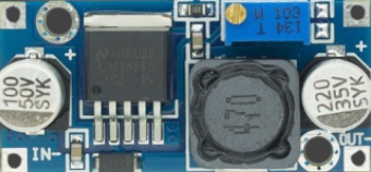
A step-down converter, also known as a buck converter, is a type of DC-DC converter that reduces voltage from a higher level to a lower level. This component is widely used to provide a stable 5V output, making it ideal for powering low-voltage electronic devices such as microcontrollers, sensors, and communication modules. Its compact size and efficiency make it a popular choice in battery-powered systems, embedded devices, and portable electronics.
Explore Projects Built with step down 5v
 Open Project in Cirkit Designer
 Open Project in Cirkit Designer
 Open Project in Cirkit Designer
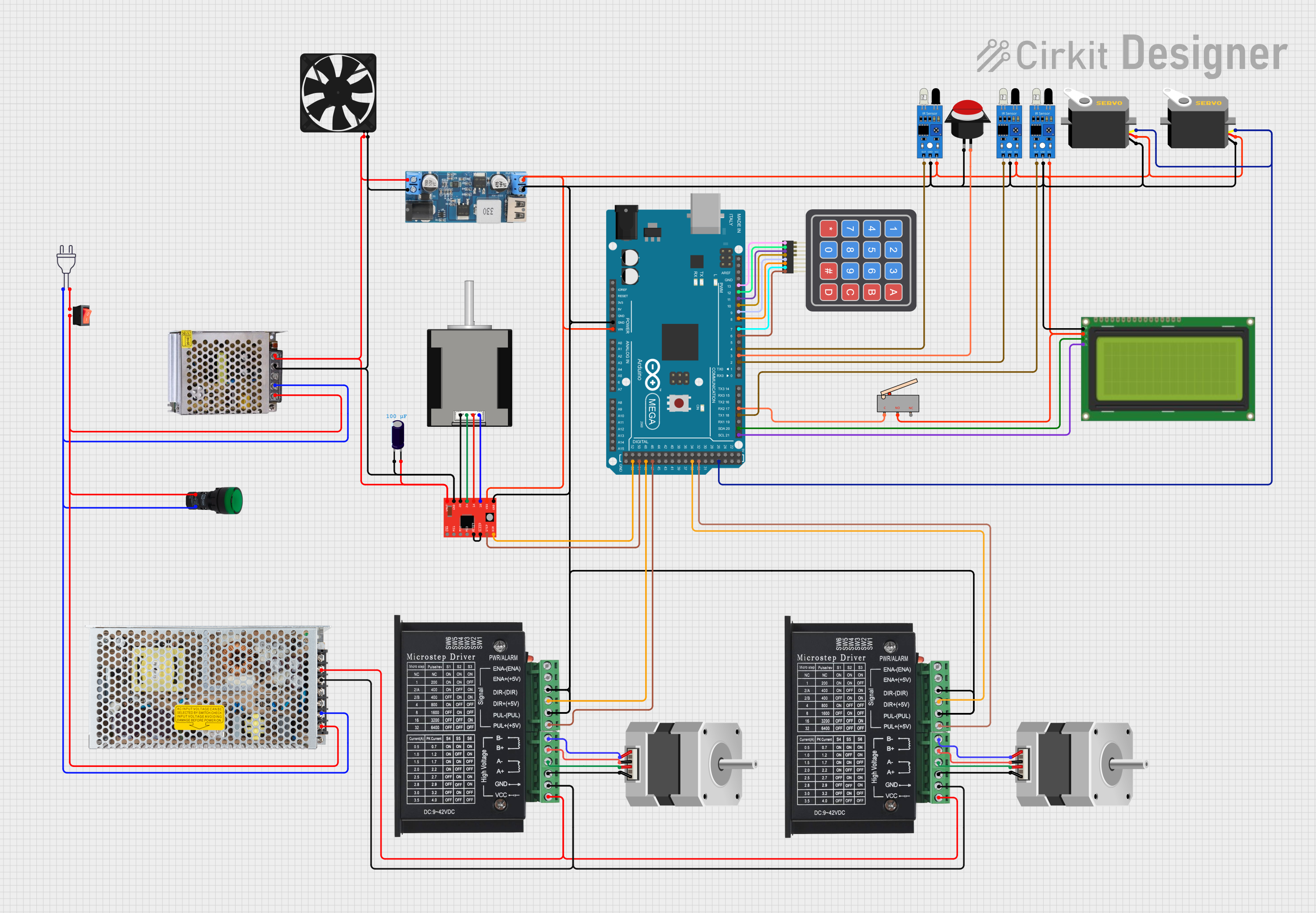 Open Project in Cirkit Designer
Explore Projects Built with step down 5v
Open Project in Cirkit DesignerOpen Project in Cirkit DesignerOpen Project in Cirkit DesignerOpen Project in Cirkit DesignerCommon Applications:
- Powering microcontrollers (e.g., Arduino, Raspberry Pi)
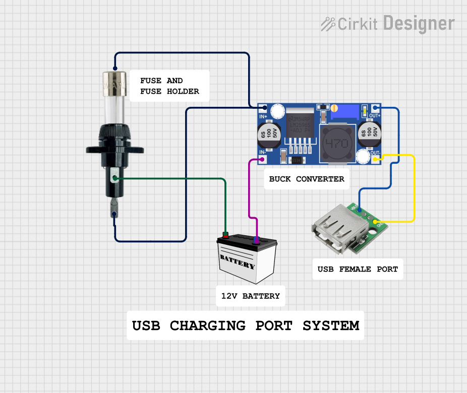
- Charging USB-powered devices
- Voltage regulation in battery-operated systems
- Supplying power to sensors and communication modules
Technical Specifications
Below are the key technical details for a typical step-down 5V converter:
| Parameter | Value |
|---|---|
| Input Voltage Range | 6V to 24V (varies by model) |
| Output Voltage | 5V (regulated) |
| Output Current | Up to 3A (check specific model) |
| Efficiency | Up to 95% |
| Switching Frequency | 150 kHz to 1 MHz (varies) |
| Operating Temperature | -40°C to +85°C |
| Dimensions | Compact (e.g., 22mm x 17mm) |
Pin Configuration and Descriptions
The step-down 5V converter typically has the following pins:
| Pin Name | Description |
|---|---|
| VIN | Input voltage pin. Connect to the higher voltage source (e.g., 12V battery). |
| GND | Ground pin. Connect to the ground of the circuit. |
| VOUT | Output voltage pin. Provides a stable 5V output for powering devices. |
| EN (optional) | Enable pin. Used to turn the converter on/off (active high). |
Usage Instructions
How to Use the Step-Down 5V Converter in a Circuit
Connect the Input Voltage (VIN):
Attach the VIN pin to a DC voltage source (e.g., a 12V battery or power supply). Ensure the input voltage is within the specified range of the converter.Connect the Ground (GND):
Connect the GND pin to the ground of your circuit. This is essential for proper operation.Connect the Output Voltage (VOUT):
Attach the VOUT pin to the device or circuit requiring a 5V power supply. Verify that the connected load does not exceed the maximum output current rating.Optional - Enable Pin (EN):
If the converter has an EN pin, connect it to a logic HIGH signal (e.g., 3.3V or 5V) to enable the converter. Leave it unconnected or pull it LOW to disable the output.
Important Considerations and Best Practices
- Input Voltage Range: Always ensure the input voltage is within the specified range to avoid damaging the converter.
- Heat Dissipation: For high-current applications, ensure proper ventilation or add a heatsink to prevent overheating.
- Capacitors: Use appropriate input and output capacitors (as recommended in the datasheet) to ensure stable operation and reduce noise.
- Polarity: Double-check the polarity of connections to avoid damaging the component or connected devices.
Example: Using the Step-Down 5V Converter with an Arduino UNO
Below is an example of how to use the step-down converter to power an Arduino UNO:
- Connect the VIN pin of the converter to a 12V DC power source.
- Connect the GND pin of the converter to the ground of the power source and the Arduino.
- Connect the VOUT pin of the converter to the 5V pin of the Arduino UNO.
Arduino Code Example
If you are using the step-down converter to power sensors or modules connected to the Arduino, here is a simple code snippet to read data from a sensor:
// Example: Reading data from a sensor powered by the step-down converter
const int sensorPin = A0; // Sensor connected to analog pin A0
int sensorValue = 0;      // Variable to store sensor reading

void setup() {
  Serial.begin(9600); // Initialize serial communication at 9600 baud
  pinMode(sensorPin, INPUT); // Set sensor pin as input
}

void loop() {
  sensorValue = analogRead(sensorPin); // Read the sensor value
  Serial.print("Sensor Value: ");      // Print the sensor value to the serial monitor
  Serial.println(sensorValue);
  delay(1000); // Wait for 1 second before the next reading
}
Troubleshooting and FAQs
Common Issues and Solutions
No Output Voltage:
- Cause: Input voltage is too low or connections are incorrect.
- Solution: Verify that the input voltage is within the specified range and check all connections.
Overheating:
- Cause: Excessive current draw or poor ventilation.
- Solution: Reduce the load current or add a heatsink to the converter.
Output Voltage Fluctuations:
- Cause: Insufficient input/output capacitors or unstable input voltage.
- Solution: Add appropriate capacitors as recommended in the datasheet and ensure a stable input voltage.
Device Not Powering On:
- Cause: EN pin is not connected or is pulled LOW.
- Solution: Connect the EN pin to a logic HIGH signal or check the datasheet for default behavior.
FAQs
Q1: Can I use the step-down converter with a 24V input?
A1: Yes, as long as the converter's input voltage range supports 24V. Check the specific model's datasheet.
Q2: What happens if I exceed the maximum output current?
A2: Exceeding the current limit may cause the converter to overheat, shut down, or become damaged. Always stay within the rated current.
Q3: Can I use this converter to power USB devices?
A3: Yes, the 5V output is suitable for USB-powered devices. Ensure the current requirements of the device are within the converter's capacity.
Q4: Is the output voltage adjustable?
A4: Some step-down converters have an adjustable output voltage. Check if your model includes a potentiometer or adjustment pin.