How to Use GL35 KV100: Examples, Pinouts, and Specs
Introduction
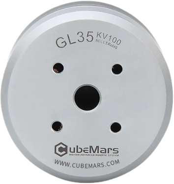
The GL35 KV100 is a high-performance brushless DC (BLDC) motor manufactured by Cubemars. Designed for precision and efficiency, this motor is ideal for applications requiring smooth operation, high torque, and low noise. Its compact size and robust construction make it suitable for robotics, drones, gimbals, and other motion control systems.
Common applications include:
- Robotics and automation systems
- Drone propulsion systems
- Camera gimbals and stabilizers
- Small electric vehicles
- Industrial machinery requiring precise motor control
Explore Projects Built with GL35 KV100


Explore Projects Built with GL35 KV100
Technical Specifications
The GL35 KV100 motor is engineered for reliability and performance. Below are its key technical details:
| Parameter | Specification |
|---|---|
| Manufacturer | Cubemars |
| Part ID | BLDC |
| Motor Type | Brushless DC (BLDC) |
| KV Rating | 100 KV (RPM/V) |
| Voltage Range | 12V - 24V |
| Maximum Current | 15A |
| Maximum Power | 360W |
| Stator Diameter | 35mm |
| Motor Weight | 120g |
| Shaft Diameter | 4mm |
| Number of Poles | 14 |
| Efficiency | >85% |
Pin Configuration and Descriptions
The GL35 KV100 motor has three primary wires for operation, as shown in the table below:
| Pin/Wire | Color | Description |
|---|---|---|
| Phase A | Yellow | Connects to the motor driver (Phase A) |
| Phase B | Green | Connects to the motor driver (Phase B) |
| Phase C | Blue | Connects to the motor driver (Phase C) |
Note: The motor requires an external electronic speed controller (ESC) for operation. Ensure the ESC is compatible with the motor's voltage and current ratings.
Usage Instructions
To use the GL35 KV100 motor in a circuit, follow these steps:
Connect the Motor to an ESC:
- Connect the three motor wires (Phase A, B, and C) to the corresponding output terminals of the ESC.
- Ensure the connections are secure to prevent signal loss or damage.
Power the ESC:
- Supply the ESC with a DC voltage within the motor's operating range (12V - 24V).
- Use a power source capable of delivering sufficient current (at least 15A).
Control the Motor:
- Use a microcontroller (e.g., Arduino UNO) or a remote control system to send PWM signals to the ESC.
- Adjust the PWM signal to control the motor's speed and direction.
Mount the Motor:
- Secure the motor to a stable surface using appropriate screws and mounts.
- Ensure the shaft is aligned with the load to avoid mechanical stress.
Arduino UNO Example Code
Below is an example of how to control the GL35 KV100 motor using an Arduino UNO and a compatible ESC:
// Example code to control the GL35 KV100 motor using Arduino UNO
// Ensure the ESC signal wire is connected to pin 9 on the Arduino

#include <Servo.h> // Include the Servo library for ESC control

Servo esc; // Create a Servo object to control the ESC

void setup() {
  esc.attach(9); // Attach the ESC signal wire to pin 9
  esc.writeMicroseconds(1000); // Send minimum throttle signal to initialize ESC
  delay(2000); // Wait for the ESC to arm (check ESC manual for arming time)
}

void loop() {
  esc.writeMicroseconds(1500); // Set throttle to 50% (adjust as needed)
  delay(5000); // Run motor at 50% throttle for 5 seconds

  esc.writeMicroseconds(1000); // Stop the motor
  delay(2000); // Wait for 2 seconds before restarting
}
Important Considerations:
- Always calibrate the ESC before use (refer to the ESC manual for calibration instructions).
- Avoid running the motor without a load for extended periods, as this may cause overheating.
- Ensure proper ventilation to prevent the motor from overheating during operation.
Troubleshooting and FAQs
Common Issues and Solutions
Motor Does Not Spin:
- Cause: Incorrect wiring or ESC not armed.
- Solution: Verify the motor wires are connected to the ESC correctly. Ensure the ESC is armed by following its initialization procedure.
Motor Spins in the Wrong Direction:
- Cause: Phase wires are connected incorrectly.
- Solution: Swap any two of the three motor wires to reverse the direction.
Motor Overheats:
- Cause: Excessive load or insufficient ventilation.
- Solution: Reduce the load on the motor and ensure proper airflow around the motor.
ESC Beeps Continuously:
- Cause: ESC is not receiving a valid signal from the microcontroller.
- Solution: Check the PWM signal connection and ensure the microcontroller is sending the correct signal.
FAQs
Can I use a battery to power the motor? Yes, you can use a LiPo battery within the voltage range of 12V to 24V. Ensure the battery can supply sufficient current.
What ESC should I use with this motor? Use an ESC rated for at least 15A and compatible with the motor's voltage range.
How do I mount the motor? Use the mounting holes on the motor's base. Ensure the motor is securely fastened to prevent vibrations.
Can I run the motor without an ESC? No, the GL35 KV100 requires an ESC to operate. Directly connecting the motor to a power source will not work.
By following this documentation, you can effectively integrate the GL35 KV100 motor into your projects and achieve optimal performance.