Cirkit Designer Logo
Cirkit Designer
Your all-in-one circuit design IDE
Home / 
Component Documentation

How to Use DC DC converter: Examples, Pinouts, and Specs

Image of DC DC converter
Cirkit Designer LogoDesign with DC DC converter in Cirkit Designer

Introduction

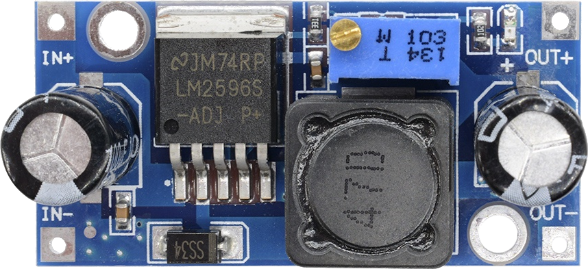
A DC-DC converter is an essential component in modern electronics, enabling devices to operate at different voltage levels from a given power supply. The Arceli DC-DC converter is designed to provide a reliable and efficient voltage conversion solution, suitable for a wide range of applications including battery-powered devices, power regulation for embedded systems, and adjustable power supplies for prototyping.

Common applications include:

  • Mobile and portable devices
  • Embedded systems
  • Power supply units
  • Automotive electronics
  • Renewable energy systems

Explore Projects Built with DC DC converter

Use Cirkit Designer to design, explore, and prototype these projects online. Some projects support real-time simulation. Click "Open Project" to start designing instantly!
DC-DC Converter and Relay Module Power Distribution System
Image of relay: A project utilizing DC DC converter in a practical application
This circuit consists of a DC-DC converter powering a 6-channel power module, which in turn supplies 5V to a 2-relay module. The power module distributes the converted voltage to the relay module, enabling it to control external devices.
Cirkit Designer LogoOpen Project in Cirkit Designer
AC to DC Micro USB Power Supply with Buck Converter
Image of ac: A project utilizing DC DC converter in a practical application
This circuit is designed to convert AC power to regulated DC power. An AC source feeds a power transformer that steps down the voltage, which is then rectified by a bridge rectifier to produce a pulsating DC. This DC is further converted to a stable DC output by a step-down buck converter, which then provides power through a Micro USB connector.
Cirkit Designer LogoOpen Project in Cirkit Designer
Battery-Powered DC-DC Converter System for Multi-Voltage Power Distribution
Image of test 1 ih: A project utilizing DC DC converter in a practical application
This circuit converts a 38.5V battery output to multiple lower voltage levels using a series of DC-DC converters and a power module. It includes an emergency stop switch for safety and distributes power to various components such as a relay module, USB ports, and a bus servo adaptor.
Cirkit Designer LogoOpen Project in Cirkit Designer
Multi-Stage Voltage Regulation and Indicator LED Circuit
Image of Subramanyak_Power_Circuit: A project utilizing DC DC converter in a practical application
This circuit is designed for power management, featuring buck and boost converters for voltage adjustment, and linear regulators for stable voltage output. It includes LEDs for status indication, and terminal blocks for external connections.
Cirkit Designer LogoOpen Project in Cirkit Designer

Explore Projects Built with DC DC converter

Use Cirkit Designer to design, explore, and prototype these projects online. Some projects support real-time simulation. Click "Open Project" to start designing instantly!
Image of relay: A project utilizing DC DC converter in a practical application
DC-DC Converter and Relay Module Power Distribution System
This circuit consists of a DC-DC converter powering a 6-channel power module, which in turn supplies 5V to a 2-relay module. The power module distributes the converted voltage to the relay module, enabling it to control external devices.
Cirkit Designer LogoOpen Project in Cirkit Designer
Image of ac: A project utilizing DC DC converter in a practical application
AC to DC Micro USB Power Supply with Buck Converter
This circuit is designed to convert AC power to regulated DC power. An AC source feeds a power transformer that steps down the voltage, which is then rectified by a bridge rectifier to produce a pulsating DC. This DC is further converted to a stable DC output by a step-down buck converter, which then provides power through a Micro USB connector.
Cirkit Designer LogoOpen Project in Cirkit Designer
Image of test 1 ih: A project utilizing DC DC converter in a practical application
Battery-Powered DC-DC Converter System for Multi-Voltage Power Distribution
This circuit converts a 38.5V battery output to multiple lower voltage levels using a series of DC-DC converters and a power module. It includes an emergency stop switch for safety and distributes power to various components such as a relay module, USB ports, and a bus servo adaptor.
Cirkit Designer LogoOpen Project in Cirkit Designer
Image of Subramanyak_Power_Circuit: A project utilizing DC DC converter in a practical application
Multi-Stage Voltage Regulation and Indicator LED Circuit
This circuit is designed for power management, featuring buck and boost converters for voltage adjustment, and linear regulators for stable voltage output. It includes LEDs for status indication, and terminal blocks for external connections.
Cirkit Designer LogoOpen Project in Cirkit Designer

Technical Specifications

Key Technical Details

  • Input Voltage Range: 2.5V to 15V DC
  • Output Voltage Range: 0.5V to 30V DC (adjustable)
  • Maximum Output Current: 3A (with heat sink)
  • Conversion Efficiency: Up to 95%
  • Switching Frequency: 150kHz
  • Operating Temperature: -40°C to +85°C

Pin Configuration and Descriptions

Pin Number Name Description
1 VIN Input voltage (2.5V to 15V DC)
2 GND Ground reference
3 VOUT Output voltage (0.5V to 30V DC, adjustable)
4 ADJ Adjustment pin for output voltage
5 EN Enable pin for turning the converter on/off

Usage Instructions

Integrating the DC-DC Converter into a Circuit

  1. Connecting Input Power:

    • Connect the positive terminal of your DC power source to the VIN pin.
    • Connect the negative terminal to the GND pin.
  2. Setting Output Voltage:

    • Adjust the output voltage by turning the potentiometer connected to the ADJ pin.
    • Use a multimeter to measure the VOUT pin and set it to the desired voltage level.
  3. Enabling the Converter:

    • The EN pin can be left floating for normal operation.
    • To switch the converter on/off via a microcontroller, connect the EN pin to a digital output pin.
  4. Connecting the Load:

    • Connect the load to the VOUT and GND pins.
    • Ensure the load does not exceed the maximum current rating of 3A.

Best Practices

  • Always verify input and output voltages with a multimeter before connecting sensitive loads.
  • Use a heat sink for applications drawing currents close to the maximum rating.
  • Place a capacitor at the output to smooth out voltage ripples if necessary.
  • Avoid placing the converter in high-temperature environments to prevent overheating.

Example Code for Arduino UNO

// Example code to enable and disable the Arceli DC-DC converter using an Arduino UNO

const int enablePin = 7; // Connect the EN pin of the converter to digital pin 7

void setup() {
  pinMode(enablePin, OUTPUT); // Set the enable pin as an output
}

void loop() {
  digitalWrite(enablePin, HIGH); // Turn on the DC-DC converter
  delay(5000); // Keep it on for 5 seconds
  
  digitalWrite(enablePin, LOW); // Turn off the DC-DC converter
  delay(5000); // Keep it off for 5 seconds
}

Troubleshooting and FAQs

Common Issues

  • Output voltage is too low or too high: Ensure the ADJ pin is correctly adjusted.
  • Converter is overheating: Check if the current draw is within the limit and if a heat sink is necessary.
  • No output voltage: Verify connections, input voltage, and if the EN pin is enabled.

Solutions and Tips

  • If the output voltage does not stabilize, add a capacitor to the output to filter noise.
  • Use thicker wires for higher currents to minimize voltage drops.
  • If the converter does not turn on, check the EN pin connection and the input voltage.

FAQs

Q: Can I use this converter to charge batteries? A: Yes, but ensure the output voltage is appropriate for the battery and that current limits are observed.

Q: Is it possible to synchronize multiple converters? A: This model does not support synchronization. You would need a converter with a sync pin for that feature.

Q: How do I know if I need a heat sink? A: If the converter is running hot or if you're drawing current near the 3A limit, a heat sink is recommended.

For further assistance, please contact Arceli support or refer to the detailed datasheet provided with the component.