
How to Use BLDC Brushless Fan Motor 5 inch: Examples, Pinouts, and Specs
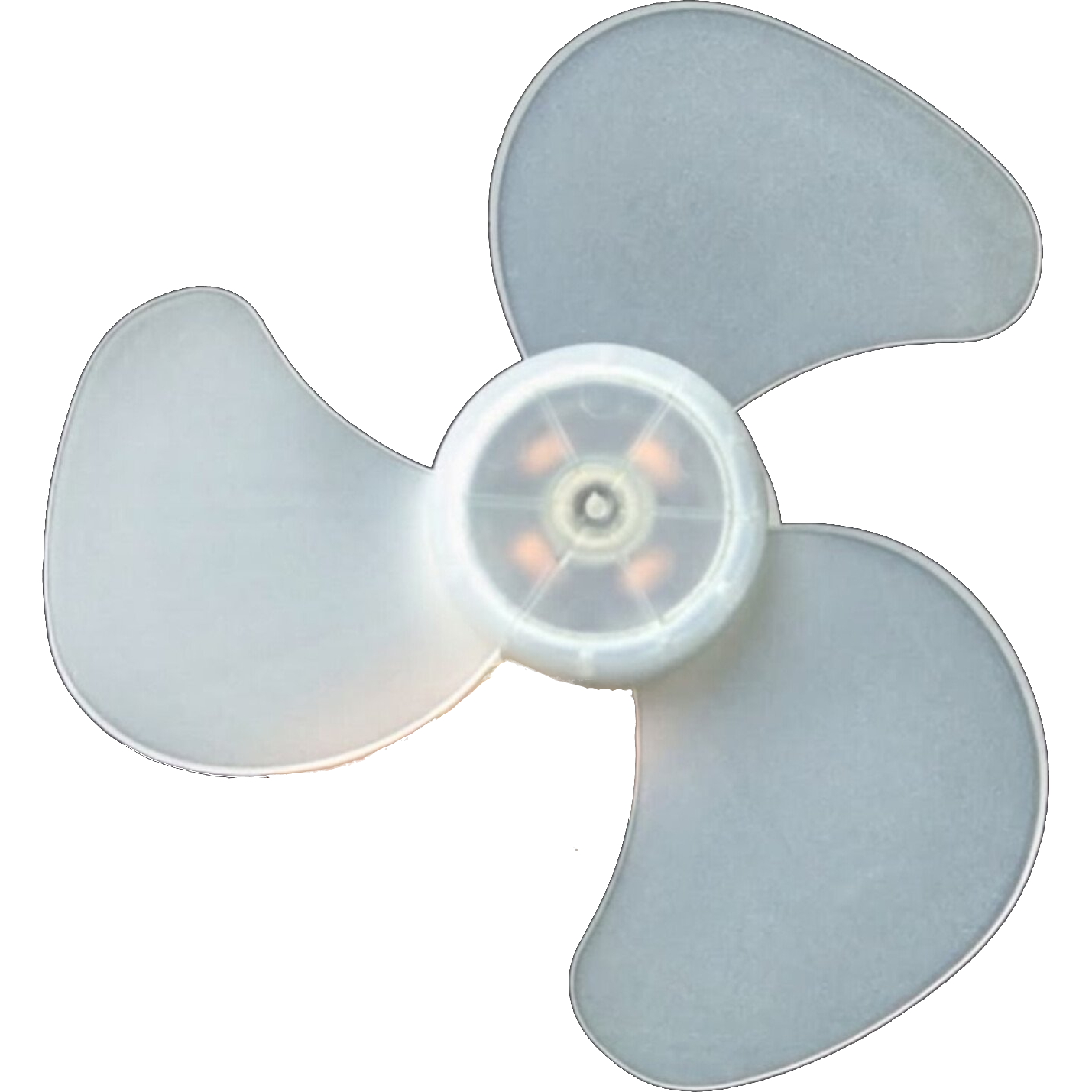
 Design with BLDC Brushless Fan Motor 5 inch in Cirkit Designer
Introduction
The 5-inch Brushless Direct Current (BLDC) Fan Motor is a highly efficient and reliable motor designed for cooling applications. Unlike traditional brushed motors, the BLDC motor operates without physical brushes, reducing wear and tear, minimizing noise, and improving overall efficiency. This motor is commonly used in electronics cooling systems, HVAC systems, and household appliances where quiet and dependable operation is essential.
Explore Projects Built with BLDC Brushless Fan Motor 5 inch
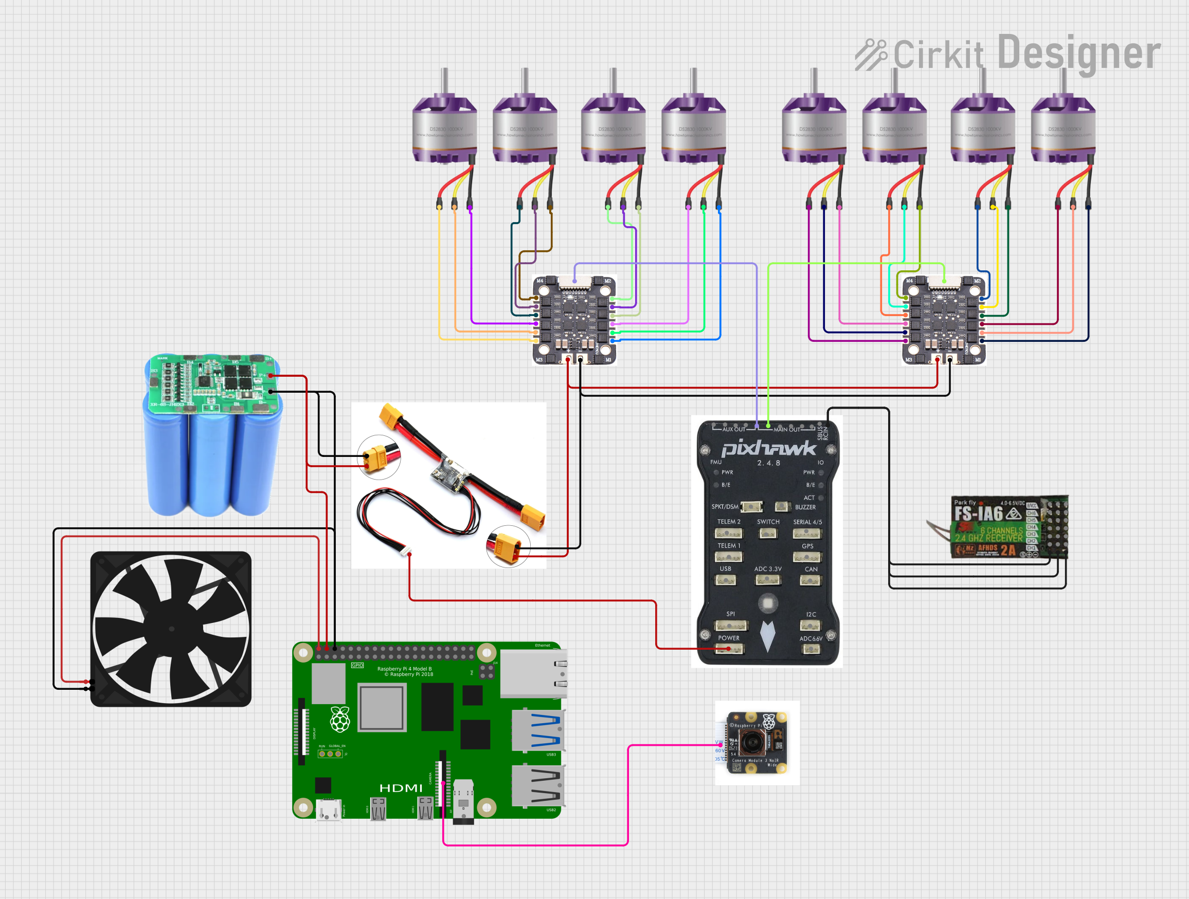 Open Project in Cirkit Designer
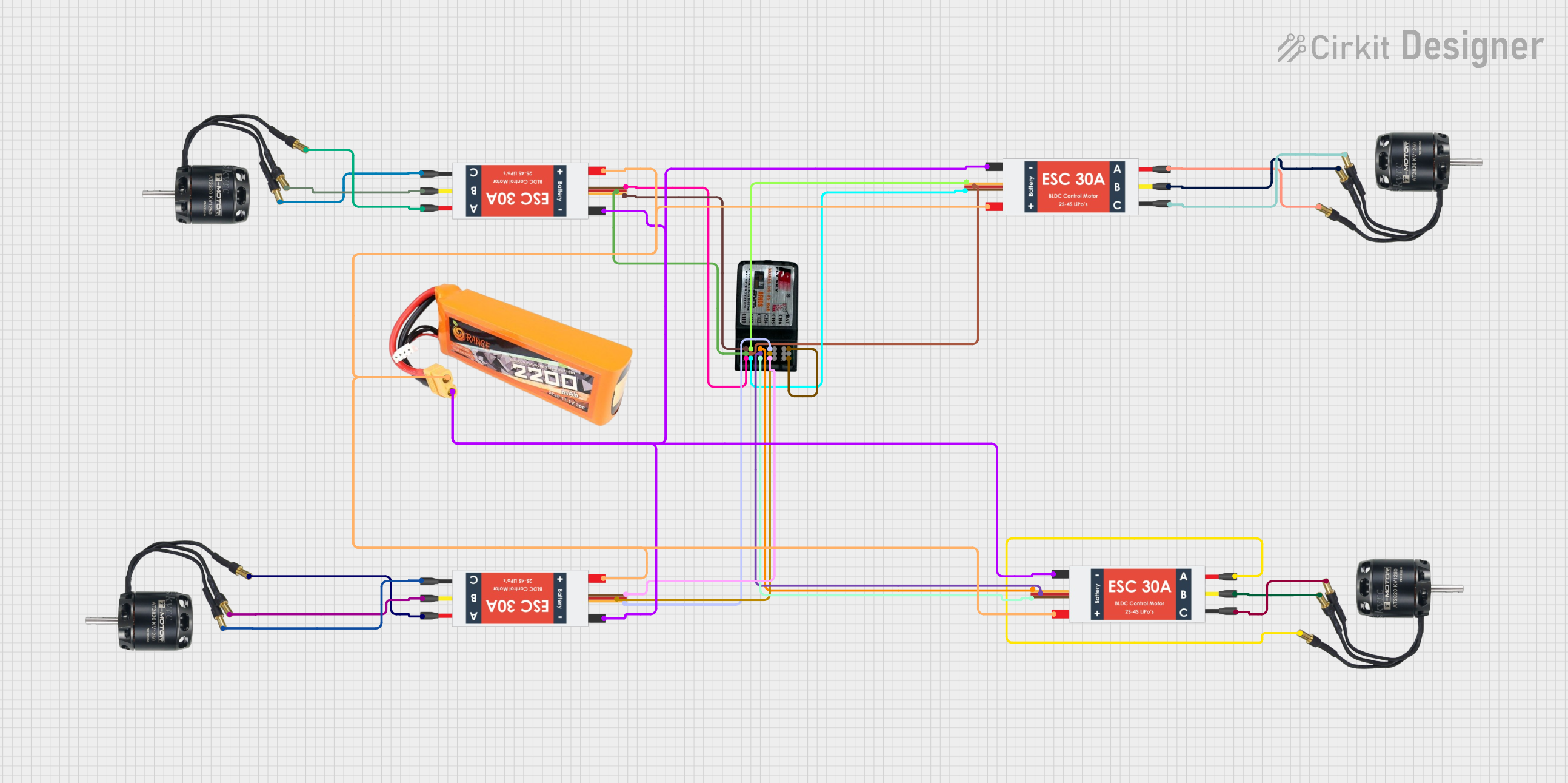 Open Project in Cirkit Designer
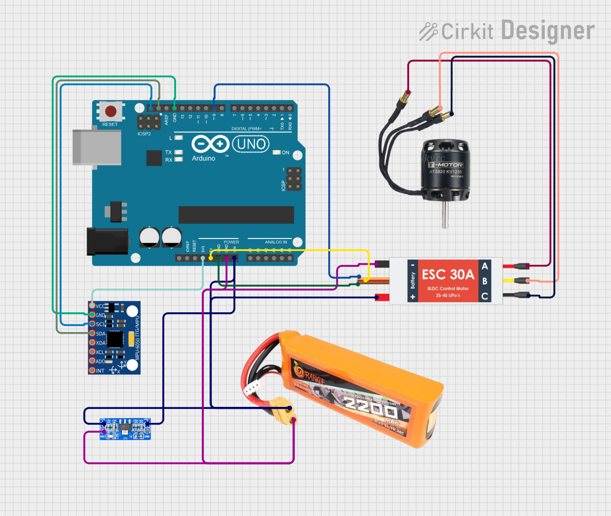 Open Project in Cirkit Designer
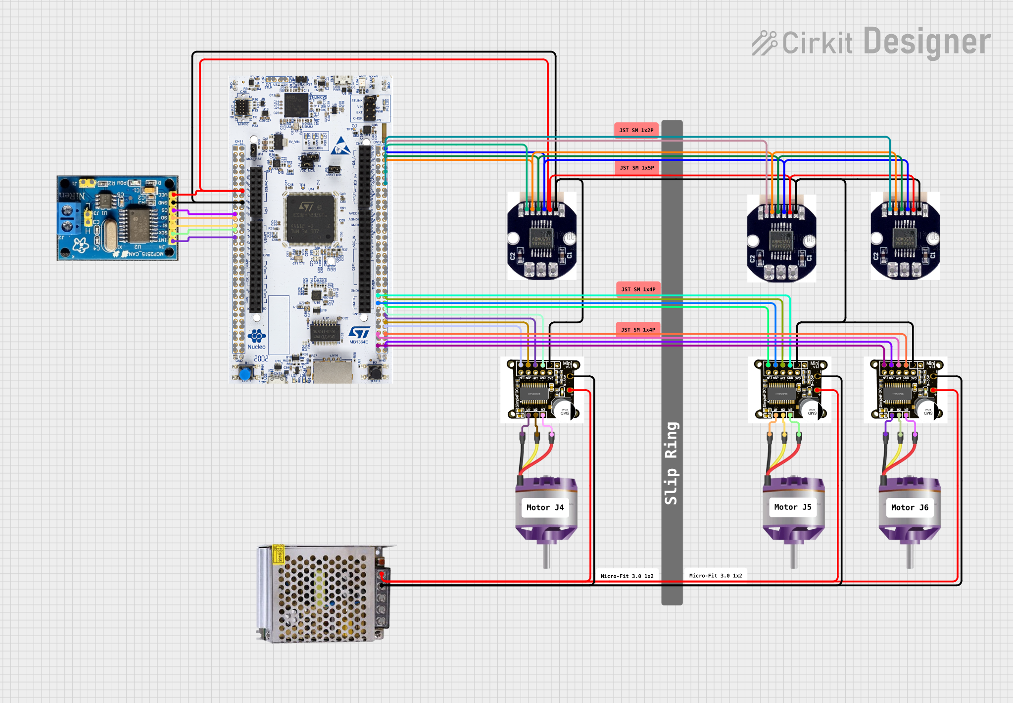 Open Project in Cirkit Designer
Explore Projects Built with BLDC Brushless Fan Motor 5 inch
Open Project in Cirkit DesignerOpen Project in Cirkit DesignerOpen Project in Cirkit DesignerOpen Project in Cirkit DesignerCommon Applications
- Cooling systems for computers, servers, and other electronics
- Ventilation in HVAC systems
- Air circulation in household appliances (e.g., air purifiers, refrigerators)
- Industrial equipment requiring compact and efficient cooling solutions
Technical Specifications
Key Specifications
| Parameter | Value |
|---|---|
| Motor Type | Brushless DC (BLDC) |
| Diameter | 5 inches |
| Operating Voltage Range | 12V to 24V DC |
| Rated Current | 0.5A to 1.2A (depending on load) |
| Power Consumption | 6W to 28W |
| Speed Range | 1,000 to 3,500 RPM |
| Noise Level | < 30 dB at 1,500 RPM |
| Bearing Type | Ball Bearing |
| Lifespan | 50,000 hours (typical) |
| Operating Temperature | -10°C to 70°C |
| Connector Type | 3-pin or 4-pin (PWM control) |
Pin Configuration
The BLDC fan motor typically comes with a 3-pin or 4-pin connector. Below is the pin configuration for both types:
3-Pin Connector
| Pin Number | Name | Description |
|---|---|---|
| 1 | VCC | Positive power supply (12V-24V DC) |
| 2 | GND | Ground |
| 3 | Tachometer | Speed feedback signal (optional) |
4-Pin Connector
| Pin Number | Name | Description |
|---|---|---|
| 1 | VCC | Positive power supply (12V-24V DC) |
| 2 | GND | Ground |
| 3 | Tachometer | Speed feedback signal (optional) |
| 4 | PWM | Pulse Width Modulation (speed control) |
Usage Instructions
How to Use the BLDC Fan Motor in a Circuit
- Power Supply: Ensure the motor is connected to a DC power supply within the operating voltage range (12V to 24V). Exceeding this range may damage the motor.
- Connection: Use the appropriate connector (3-pin or 4-pin) to interface with your circuit or controller.
- For a 3-pin motor, connect VCC to the positive terminal, GND to the ground, and optionally use the tachometer pin for speed monitoring.
- For a 4-pin motor, connect the PWM pin to a microcontroller or PWM signal generator for speed control.
- Speed Control: If using a 4-pin motor, generate a PWM signal (typically 25 kHz) to control the fan speed. A duty cycle of 0% stops the motor, while 100% runs it at full speed.
- Mounting: Secure the motor in place using screws or brackets to prevent vibration during operation.
Important Considerations
- Voltage Regulation: Use a stable DC power supply to avoid voltage fluctuations that could damage the motor.
- Heat Dissipation: Ensure proper ventilation around the motor to prevent overheating.
- PWM Signal: When using PWM control, ensure the signal frequency matches the motor's specifications (typically 25 kHz).
- Polarity: Double-check the polarity of the power connections to avoid reversing the voltage, which can damage the motor.
Example: Controlling the Motor with Arduino UNO
Below is an example of how to control the speed of a 4-pin BLDC fan motor using an Arduino UNO:
// Define the PWM pin connected to the motor's PWM input
const int pwmPin = 9; // Pin 9 on Arduino UNO

void setup() {
  pinMode(pwmPin, OUTPUT); // Set the PWM pin as an output
}

void loop() {
  // Gradually increase the fan speed
  for (int dutyCycle = 0; dutyCycle <= 255; dutyCycle += 5) {
    analogWrite(pwmPin, dutyCycle); // Write PWM signal to the motor
    delay(50); // Wait 50ms before increasing the speed
  }

  // Gradually decrease the fan speed
  for (int dutyCycle = 255; dutyCycle >= 0; dutyCycle -= 5) {
    analogWrite(pwmPin, dutyCycle); // Write PWM signal to the motor
    delay(50); // Wait 50ms before decreasing the speed
  }
}
Notes:
- The
analogWrite()function generates a PWM signal with an approximate frequency of 490 Hz on most Arduino pins. This is sufficient for basic speed control but may not be optimal for all BLDC motors. Check the motor's datasheet for the recommended PWM frequency. - Use an external transistor or MOSFET if the motor's current exceeds the Arduino's pin current rating.
Troubleshooting and FAQs
Common Issues and Solutions
Motor Does Not Spin
- Cause: Incorrect wiring or insufficient power supply.
- Solution: Verify the connections and ensure the power supply meets the motor's voltage and current requirements.
Excessive Noise or Vibration
- Cause: Loose mounting or damaged bearings.
- Solution: Secure the motor properly and inspect for physical damage.
Overheating
- Cause: Prolonged operation at high speeds or inadequate ventilation.
- Solution: Reduce the duty cycle of the PWM signal or improve airflow around the motor.
PWM Control Not Working
- Cause: Incorrect PWM frequency or wiring.
- Solution: Verify the PWM signal frequency and ensure the PWM pin is correctly connected.
FAQs
Q: Can I use a 3-pin motor with PWM control?
A: No, 3-pin motors do not have a dedicated PWM input. Speed control for 3-pin motors can only be achieved by varying the supply voltage.Q: What is the purpose of the tachometer pin?
A: The tachometer pin provides a feedback signal (usually a square wave) that indicates the motor's speed. This can be used for monitoring or closed-loop control.Q: Can I run the motor at 5V?
A: No, the motor requires a minimum of 12V to operate correctly. Running it below the specified voltage range may result in poor performance or failure to start.Q: How do I calculate the RPM from the tachometer signal?
A: The tachometer typically outputs a signal with a frequency proportional to the motor's speed. Refer to the motor's datasheet for the pulses-per-revolution (PPR) value, and use the formula:RPM = (Frequency × 60) / PPR.
This concludes the documentation for the 5-inch BLDC Brushless Fan Motor.