How to Use I2C module: Examples, Pinouts, and Specs
Introduction
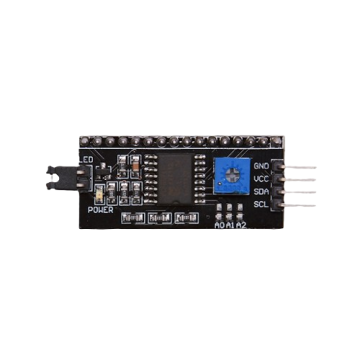
The I2C (Inter-Integrated Circuit) module is a serial communication protocol that enables data exchange between microcontrollers and various peripherals over a two-wire bus. It is widely used in embedded systems for connecting low-speed devices like sensors, EEPROMs, and displays. The I2C protocol supports multiple masters and slaves, allowing for complex communication networks with simple wiring.
Explore Projects Built with I2C module
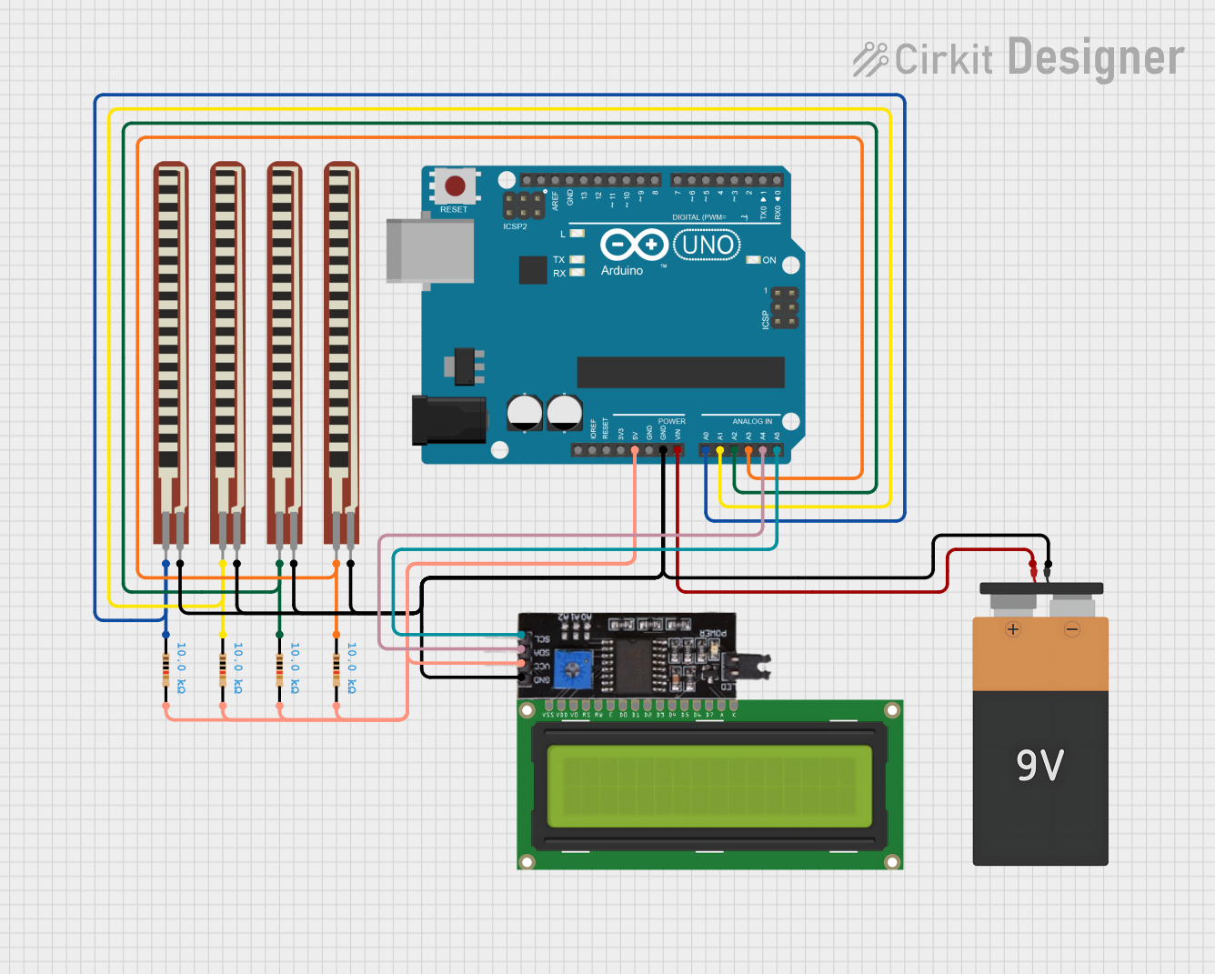
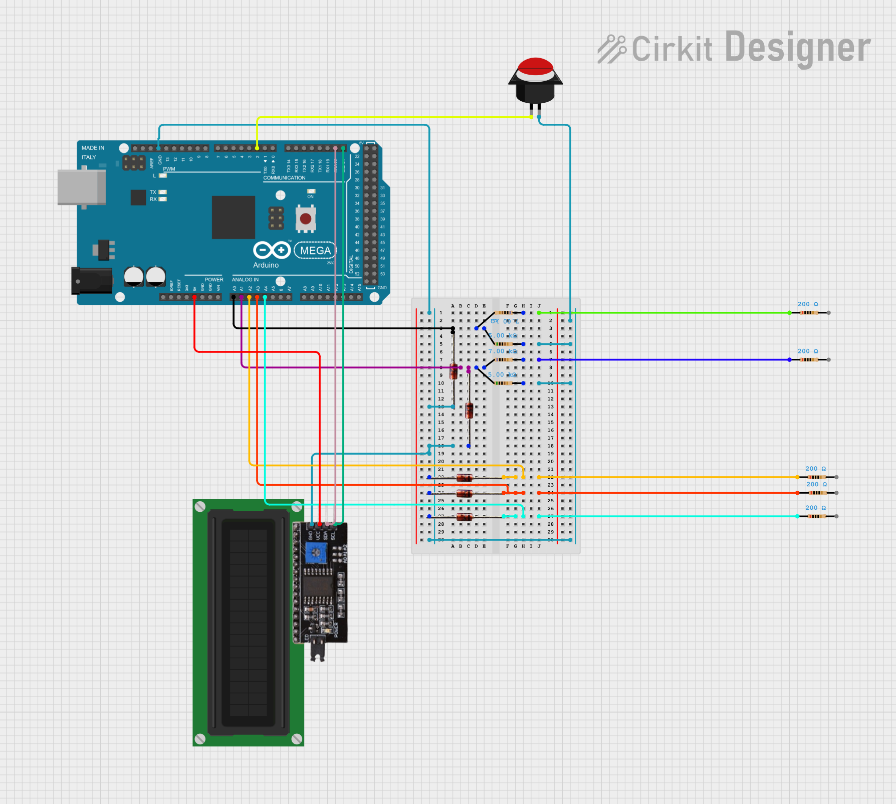

Explore Projects Built with I2C module
Common Applications and Use Cases
- Sensor data reading (temperature, pressure, etc.)
- Display control (LCD, OLED screens)
- Real-time clock settings
- EEPROM read/write operations
Technical Specifications
Key Technical Details
- Standard Modes: Standard (100 kbps), Fast (400 kbps), Fast Plus (1 Mbps)
- Voltage Levels: Typically 3.3V or 5V (logic level dependent on the specific module)
- Bus Topology: Multi-master, multi-slave
- Maximum Devices: Up to 112 devices (7-bit addressing mode)
Pin Configuration and Descriptions
| Pin Name | Description |
|---|---|
| SDA | Serial Data Line, bidirectional data transfer |
| SCL | Serial Clock Line, clock signal provided by master |
| VCC | Power supply (3.3V or 5V depending on module) |
| GND | Ground |
Usage Instructions
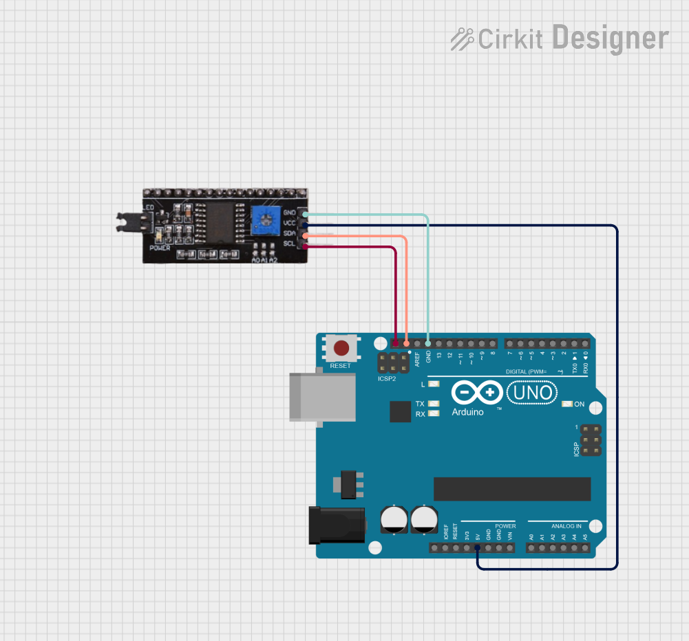
How to Use the Component in a Circuit
- Connect Power: Attach VCC to the power supply and GND to the common ground in the circuit.
- Interface with Microcontroller: Connect SDA and SCL pins to the corresponding SDA and SCL pins on the microcontroller.
- Pull-up Resistors: Attach pull-up resistors (typically 4.7kΩ to 10kΩ) to both SDA and SCL lines to VCC. These are sometimes built into the module.
Important Considerations and Best Practices
- Addressing: Ensure each I2C device has a unique address if multiple devices are on the same bus.
- Cable Length: Keep the I2C bus length short to minimize signal degradation and interference.
- Bus Speed: Select an appropriate bus speed considering the capacitance of the bus and the operational speed of the devices.
Example Code for Arduino UNO
#include <Wire.h> // Include the I2C library

void setup() {
  Wire.begin(); // Join the bus as a master or a slave
  Serial.begin(9600); // Start serial communication at 9600 baud
}

void loop() {
  Wire.beginTransmission(0x50); // Begin transmission to a device with address 0x50
  Wire.write(byte(0x00)); // Write a byte to the I2C bus
  Wire.endTransmission(); // End transmission

  Wire.requestFrom(0x50, 1); // Request 1 byte from the device at address 0x50
  while(Wire.available()) { // While there is data available to read
    char c = Wire.read(); // Read a byte
    Serial.println(c); // Print the byte to the Serial monitor
  }

  delay(1000); // Wait for 1000 milliseconds
}
Troubleshooting and FAQs
Common Issues Users Might Face
- No Communication: Check connections, ensure pull-up resistors are in place, and verify device addresses.
- Data Corruption: Reduce bus speed, check for proper grounding, and ensure there is no interference.
- Device Not Recognized: Confirm that the device is powered and correctly addressed.
Solutions and Tips for Troubleshooting
- Use an oscilloscope or logic analyzer to inspect the SDA and SCL lines for proper signaling.
- Check for soldering issues or loose connections that may affect communication.
- Ensure that the library used for I2C communication is compatible with your microcontroller.
FAQs
Q: Can I connect multiple masters to an I2C bus? A: Yes, the I2C protocol supports multi-master configurations, but careful management of bus arbitration and collision detection is necessary.
Q: How do I find the address of my I2C device? A: The address is usually specified in the device's datasheet. Alternatively, you can use an I2C scanner sketch to find connected devices on the bus.
Q: What are pull-up resistors, and why are they necessary? A: Pull-up resistors are used to ensure that the bus lines are at a defined logic level when no device is actively driving them. They are necessary for the proper operation of the I2C bus.