Cirkit Designer Logo
Cirkit Designer
Your all-in-one circuit design IDE
Home / 
Component Documentation

How to Use Ambient light sensor: Examples, Pinouts, and Specs

Image of Ambient light sensor
Cirkit Designer LogoDesign with Ambient light sensor in Cirkit Designer

Introduction

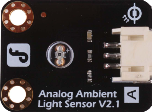
An ambient light sensor (ALS) is an electronic component that measures the intensity of the light in its environment and provides a corresponding output, typically in the form of an analog or digital signal. These sensors are widely used in devices such as smartphones, laptops, and smart home systems to adjust screen brightness and control lighting conditions, enhancing user comfort and energy efficiency.

Explore Projects Built with Ambient light sensor

Use Cirkit Designer to design, explore, and prototype these projects online. Some projects support real-time simulation. Click "Open Project" to start designing instantly!
Arduino Nano Controlled Ambient Light Sensing and NeoPixel Display
Image of GuesturLED: A project utilizing Ambient light sensor in a practical application
This circuit features an Arduino Nano microcontroller interfaced with an APDS-9930 Proximity and Ambient Light Sensor for sensing environmental light and proximity. The Arduino Nano also controls an Adafruit Quarter 60 NeoPixel Ring, likely for visual feedback or display purposes. The sensor communicates with the Arduino via I2C (SDA and SCL connections), and the NeoPixel Ring is driven by a digital output (D8) from the Arduino.
Cirkit Designer LogoOpen Project in Cirkit Designer
Raspberry Pi 5 Ambient Light Sensor System
Image of light sensor: A project utilizing Ambient light sensor in a practical application
This circuit connects a Raspberry Pi 5 to an ambient light sensor. The Raspberry Pi provides power and ground to the sensor, and communicates with it using I2C protocol through GPIO pins 2 (SDA) and 3 (SCL), with an interrupt line connected to GPIO pin 4.
Cirkit Designer LogoOpen Project in Cirkit Designer
Arduino UNO Based Ambient Light Monitoring with I2C LCD Display
Image of intensity: A project utilizing Ambient light sensor in a practical application
This circuit features an Arduino UNO microcontroller connected to a BH1750 light intensity sensor and a 20x4 LCD display, both interfaced via I2C communication. The Arduino is programmed to read the ambient light level from the BH1750 sensor and display the readings in lux on the LCD. The circuit is designed for monitoring and displaying real-time light intensity data.
Cirkit Designer LogoOpen Project in Cirkit Designer
Arduino UNO-Based Smart Light Controller with PID and LCD Display
Image of Light Dimmer Arduino: A project utilizing Ambient light sensor in a practical application
This circuit uses an Arduino UNO to control the brightness of an LED based on ambient light levels detected by a light sensor. The system includes multiple potentiometers to adjust the PID control parameters, and an LCD display to show real-time light intensity and PID values.
Cirkit Designer LogoOpen Project in Cirkit Designer

Explore Projects Built with Ambient light sensor

Use Cirkit Designer to design, explore, and prototype these projects online. Some projects support real-time simulation. Click "Open Project" to start designing instantly!
Image of GuesturLED: A project utilizing Ambient light sensor in a practical application
Arduino Nano Controlled Ambient Light Sensing and NeoPixel Display
This circuit features an Arduino Nano microcontroller interfaced with an APDS-9930 Proximity and Ambient Light Sensor for sensing environmental light and proximity. The Arduino Nano also controls an Adafruit Quarter 60 NeoPixel Ring, likely for visual feedback or display purposes. The sensor communicates with the Arduino via I2C (SDA and SCL connections), and the NeoPixel Ring is driven by a digital output (D8) from the Arduino.
Cirkit Designer LogoOpen Project in Cirkit Designer
Image of light sensor: A project utilizing Ambient light sensor in a practical application
Raspberry Pi 5 Ambient Light Sensor System
This circuit connects a Raspberry Pi 5 to an ambient light sensor. The Raspberry Pi provides power and ground to the sensor, and communicates with it using I2C protocol through GPIO pins 2 (SDA) and 3 (SCL), with an interrupt line connected to GPIO pin 4.
Cirkit Designer LogoOpen Project in Cirkit Designer
Image of intensity: A project utilizing Ambient light sensor in a practical application
Arduino UNO Based Ambient Light Monitoring with I2C LCD Display
This circuit features an Arduino UNO microcontroller connected to a BH1750 light intensity sensor and a 20x4 LCD display, both interfaced via I2C communication. The Arduino is programmed to read the ambient light level from the BH1750 sensor and display the readings in lux on the LCD. The circuit is designed for monitoring and displaying real-time light intensity data.
Cirkit Designer LogoOpen Project in Cirkit Designer
Image of Light Dimmer Arduino: A project utilizing Ambient light sensor in a practical application
Arduino UNO-Based Smart Light Controller with PID and LCD Display
This circuit uses an Arduino UNO to control the brightness of an LED based on ambient light levels detected by a light sensor. The system includes multiple potentiometers to adjust the PID control parameters, and an LCD display to show real-time light intensity and PID values.
Cirkit Designer LogoOpen Project in Cirkit Designer

Common Applications and Use Cases

  • Automatic brightness control for displays
  • Energy-saving lighting systems
  • Security lighting
  • Daylight harvesting in building automation

Technical Specifications

Key Technical Details

  • Voltage Range: Typically 1.8V to 3.6V
  • Current Consumption: Low, often in the microampere range
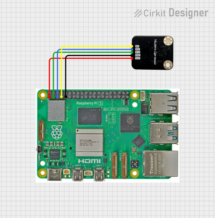
  • Output: Analog voltage or digital (I2C, PWM)
  • Spectral Response: Similar to the human eye (photopic response)
  • Ambient Light Range: From darkness (<1 lux) to bright sunlight (>100,000 lux)

Pin Configuration and Descriptions

Pin Number Name Description
1 VDD Power supply voltage
2 OUT Analog or digital output signal
3 GND Ground connection

Usage Instructions

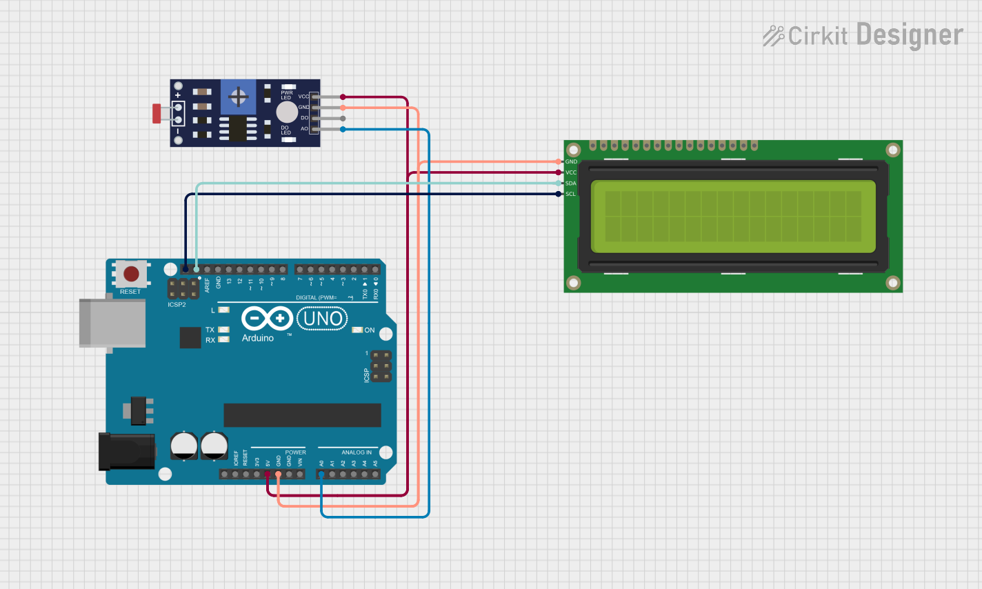
How to Use the Component in a Circuit

  1. Power Supply: Connect the VDD pin to a power source within the sensor's voltage range.
  2. Ground: Connect the GND pin to the ground of the circuit.
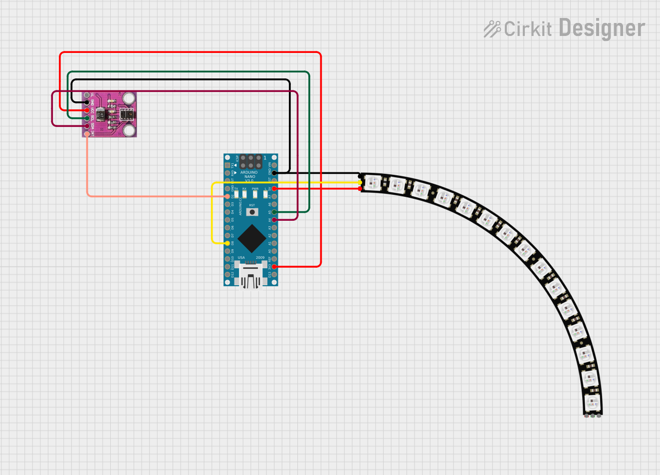
  3. Output Signal: Connect the OUT pin to an analog input of a microcontroller for analog sensors, or to the corresponding communication pins for digital sensors (e.g., I2C).

Important Considerations and Best Practices

  • Ensure that the power supply voltage does not exceed the sensor's maximum rating.
  • Place the sensor away from direct light sources that could saturate the sensor.
  • For analog sensors, use a microcontroller with an ADC (Analog-to-Digital Converter) to read the output voltage.
  • For digital sensors, ensure proper communication setup (e.g., I2C address configuration).

Example Code for Arduino UNO

// Include the Wire library for I2C communication (if digital sensor)
#include <Wire.h>

// Define the I2C address of the sensor (if applicable)
#define SENSOR_I2C_ADDRESS 0x10

void setup() {
  // Initialize serial communication for debugging
  Serial.begin(9600);

  // Initialize I2C communication (if digital sensor)
  Wire.begin();

  // Configure sensor settings (if necessary)
}

void loop() {
  int lightLevel;

  // Read the light level from the sensor
  lightLevel = readAmbientLight();

  // Print the light level to the Serial Monitor
  Serial.println(lightLevel);

  // Wait for a short period before reading again
  delay(500);
}

// Function to read the ambient light level from the sensor
int readAmbientLight() {
  // For analog sensors:
  // return analogRead(A0); // Replace A0 with the actual analog pin connected

  // For digital sensors:
  // Implement I2C communication to read the light level
  // This is a placeholder for the actual implementation
  return 0;
}

Troubleshooting and FAQs

Common Issues Users Might Face

  • Sensor not responding: Check connections and ensure the power supply is within the specified range.
  • Inaccurate readings: Verify that the sensor is not placed near a direct light source or in a position where it can be easily shaded.
  • Noisy signal: Use capacitors to filter the power supply and ensure stable readings.

Solutions and Tips for Troubleshooting

  • Double-check wiring, especially the VDD and GND connections.
  • Use a multimeter to verify the voltage at the sensor's power pin.
  • For digital sensors, check the I2C address and ensure no address conflict with other devices on the bus.

FAQs

Q: Can the ambient light sensor be used outdoors? A: Yes, but ensure the sensor's ambient light range is suitable for outdoor light levels and that it is protected from the elements.

Q: How do I calibrate the sensor? A: Calibration procedures vary by sensor model. Refer to the manufacturer's datasheet for specific instructions.

Q: What is the lifespan of an ambient light sensor? A: ALS devices typically have a long operational life, but it can be affected by operating conditions such as temperature and exposure to harsh lighting.