
How to Use ESP 32: Examples, Pinouts, and Specs
 Design with ESP 32 in Cirkit Designer
Introduction
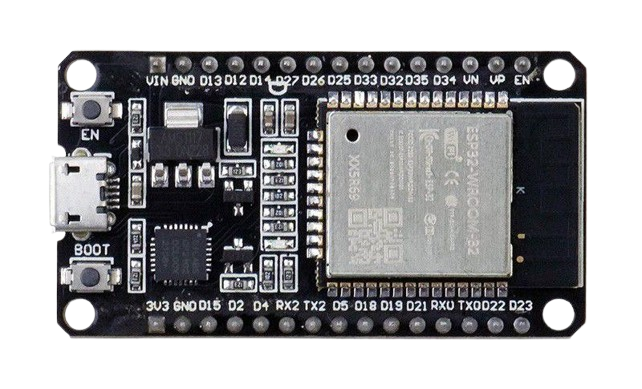
The ESP32, manufactured by NodeMCU (Part ID: ESP32), is a low-cost, low-power system on a chip (SoC) designed for IoT applications and embedded systems. It features integrated Wi-Fi and Bluetooth capabilities, making it a versatile choice for wireless communication and smart device projects. The ESP32 is widely used in applications such as home automation, wearable devices, industrial IoT, and robotics.
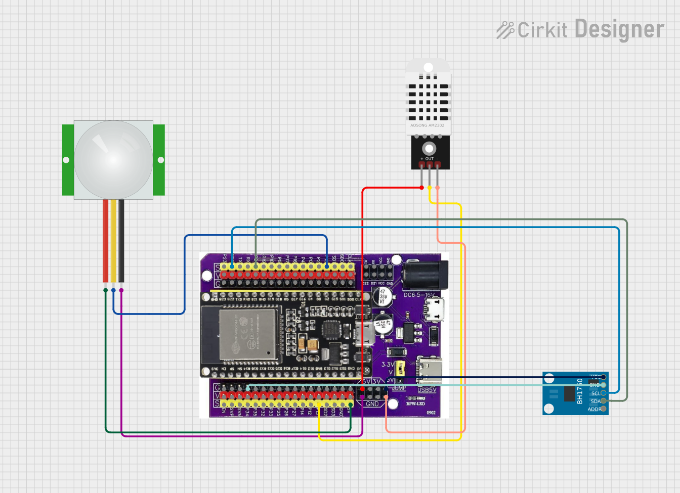
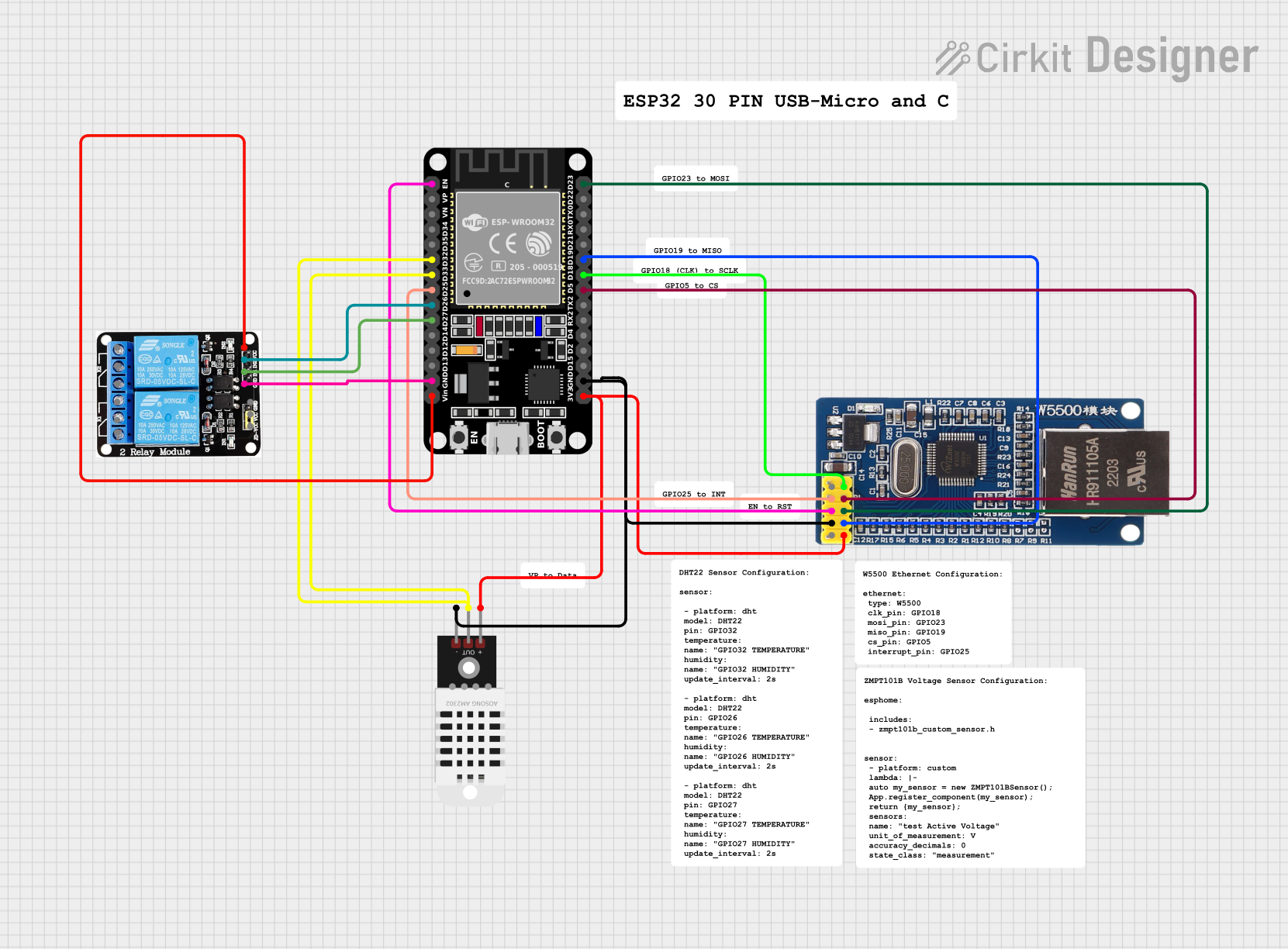
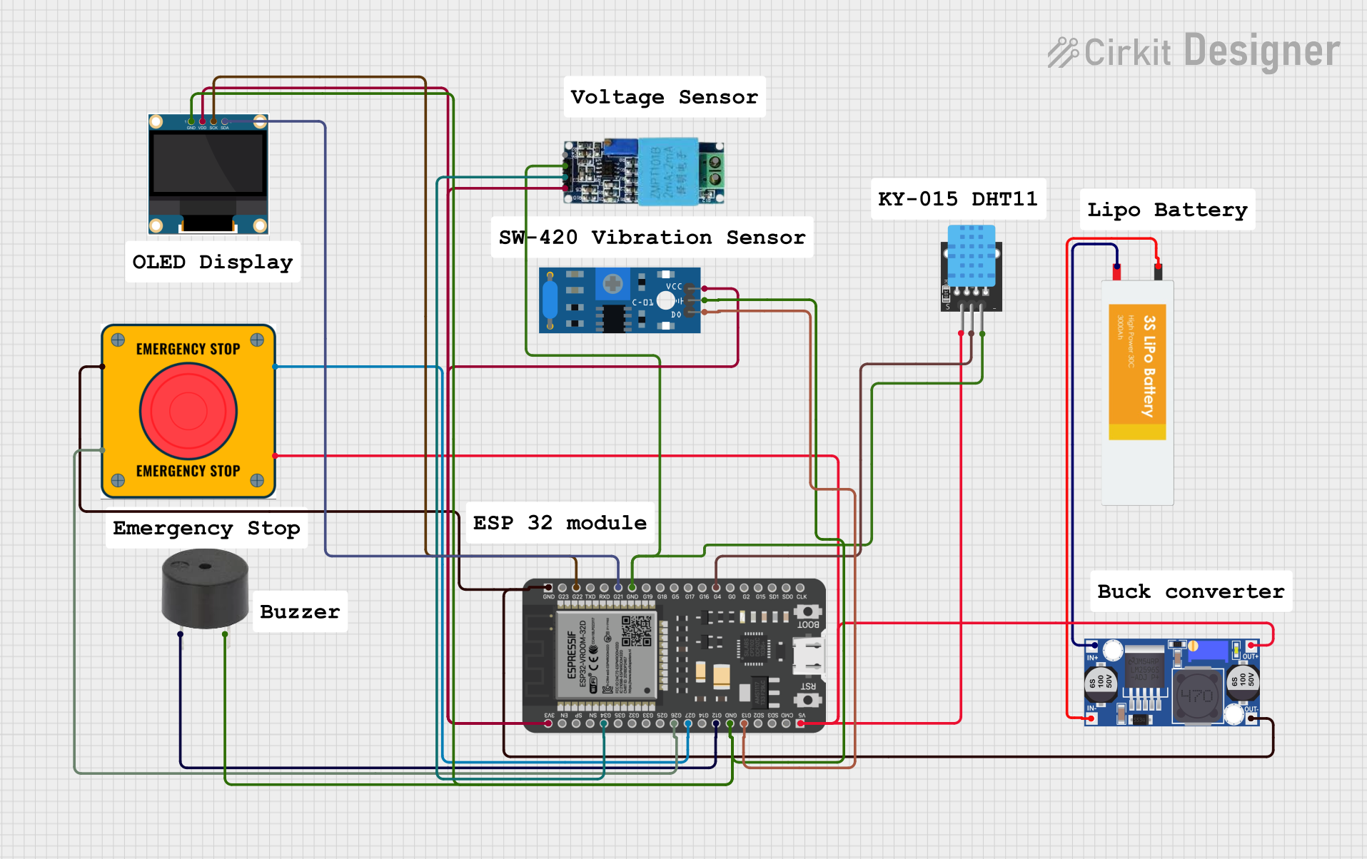
Explore Projects Built with ESP 32
 Open Project in Cirkit Designer
 Open Project in Cirkit Designer
 Open Project in Cirkit Designer
 Open Project in Cirkit Designer
Explore Projects Built with ESP 32
Open Project in Cirkit DesignerOpen Project in Cirkit DesignerOpen Project in Cirkit DesignerOpen Project in Cirkit DesignerCommon Applications:
- Smart home devices (e.g., smart lights, thermostats)
- IoT sensors and data loggers
- Wireless communication hubs
- Robotics and automation systems
- Wearable technology
Technical Specifications
Key Technical Details:
| Parameter | Specification |
|---|---|
| Microcontroller | Tensilica Xtensa LX6 dual-core (or single-core) |
| Clock Speed | Up to 240 MHz |
| Flash Memory | 4 MB (varies by model) |
| SRAM | 520 KB |
| Wi-Fi Standard | 802.11 b/g/n |
| Bluetooth Version | Bluetooth 4.2 and BLE |
| Operating Voltage | 3.3V |
| GPIO Pins | 34 |
| ADC Channels | 18 |
| DAC Channels | 2 |
| Communication Interfaces | UART, SPI, I2C, I2S, CAN, PWM |
| Power Consumption | Ultra-low power (varies by mode) |
Pin Configuration and Descriptions:
The ESP32 has multiple GPIO pins, each capable of serving various functions. Below is a summary of the pin configuration:
| Pin Number | Pin Name | Functionality |
|---|---|---|
| 1 | EN | Enable pin (active high) |
| 2 | GPIO0 | General-purpose I/O, boot mode select |
| 3 | GPIO1 | UART TX, general-purpose I/O |
| 4 | GPIO2 | General-purpose I/O, boot mode select |
| 5 | GPIO3 | UART RX, general-purpose I/O |
| ... | ... | ... (Refer to the full datasheet for all pins) |
Note: Many GPIO pins are multiplexed, meaning they can serve multiple functions depending on the configuration.
Usage Instructions
How to Use the ESP32 in a Circuit:
Powering the ESP32:
- The ESP32 operates at 3.3V. Ensure your power supply provides a stable 3.3V to avoid damaging the chip.
- If using a USB connection, the onboard voltage regulator will handle the conversion.
Connecting to Peripherals:
- Use GPIO pins to connect sensors, actuators, or other peripherals.
- For analog inputs, use the ADC pins (e.g., GPIO36 or GPIO39).
- For PWM signals, configure any GPIO pin that supports PWM output.
Programming the ESP32:
- The ESP32 can be programmed using the Arduino IDE or the ESP-IDF (Espressif IoT Development Framework).
- Install the necessary board support package (BSP) for ESP32 in the Arduino IDE.
Wi-Fi and Bluetooth Setup:
- Use the built-in libraries (e.g.,
WiFi.hfor Wi-Fi andBluetoothSerial.hfor Bluetooth) to configure wireless communication.
- Use the built-in libraries (e.g.,
Example Code for Arduino IDE:
The following example demonstrates how to connect the ESP32 to a Wi-Fi network and print the IP address:
#include <WiFi.h> // Include the Wi-Fi library

const char* ssid = "Your_SSID";       // Replace with your Wi-Fi network name
const char* password = "Your_Password"; // Replace with your Wi-Fi password

void setup() {
  Serial.begin(115200); // Initialize serial communication at 115200 baud
  delay(1000);          // Wait for a moment to stabilize

  Serial.println("Connecting to Wi-Fi...");
  WiFi.begin(ssid, password); // Start Wi-Fi connection

  while (WiFi.status() != WL_CONNECTED) {
    delay(500); // Wait until the connection is established
    Serial.print(".");
  }

  Serial.println("\nWi-Fi connected!");
  Serial.print("IP Address: ");
  Serial.println(WiFi.localIP()); // Print the assigned IP address
}

void loop() {
  // Add your main code here
}
Important Considerations:
- Voltage Levels: Ensure all connected peripherals operate at 3.3V logic levels. Use level shifters if interfacing with 5V devices.
- Boot Mode: GPIO0 must be pulled low during boot to enter programming mode.
- Power Consumption: Use deep sleep mode to minimize power usage in battery-powered applications.
Troubleshooting and FAQs
Common Issues and Solutions:
ESP32 Not Connecting to Wi-Fi:
- Cause: Incorrect SSID or password.
- Solution: Double-check the credentials in your code. Ensure the Wi-Fi network is active and within range.
Serial Monitor Not Displaying Output:
- Cause: Incorrect baud rate or COM port selection.
- Solution: Verify the baud rate in the Serial Monitor matches the
Serial.begin()value in your code. Ensure the correct COM port is selected.
ESP32 Not Entering Programming Mode:
- Cause: GPIO0 not pulled low during boot.
- Solution: Hold the "BOOT" button on the ESP32 board while pressing the "EN" (reset) button.
Overheating:
- Cause: Excessive current draw or improper power supply.
- Solution: Ensure the power supply provides sufficient current (at least 500mA). Avoid short circuits on GPIO pins.
FAQs:
Q: Can the ESP32 operate on 5V?
- A: No, the ESP32 operates at 3.3V. Applying 5V to GPIO pins can damage the chip.
Q: How many devices can the ESP32 connect to via Bluetooth?
- A: The ESP32 supports up to 7 simultaneous Bluetooth connections in BLE mode.
Q: Can I use the ESP32 for audio processing?
- A: Yes, the ESP32 supports I2S for audio input/output and has sufficient processing power for basic audio tasks.
Q: What is the maximum Wi-Fi range of the ESP32?
- A: The range depends on environmental factors but typically extends up to 100 meters in open spaces.
This documentation provides a comprehensive overview of the ESP32, ensuring users can effectively integrate it into their projects. For more advanced features, refer to the official ESP32 datasheet and programming guides.