How to Use 테무 전원 스위치 8개 버턴: Examples, Pinouts, and Specs
Introduction
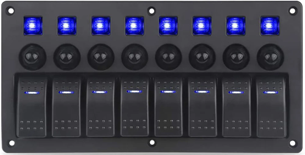
The 테무 전원 스위치 8개 버턴 is a versatile power switch module designed to control up to 8 devices or circuits independently. Each button on the module acts as a toggle switch, enabling or disabling the connected load. This component is ideal for applications requiring centralized control of multiple devices, such as home automation systems, robotics, and industrial equipment.
Explore Projects Built with 테무 전원 스위치 8개 버턴


Explore Projects Built with 테무 전원 스위치 8개 버턴
Common Applications
- Home automation (e.g., controlling lights, fans, or appliances)
- Robotics (e.g., activating motors or sensors)
- Industrial control systems
- Prototyping and testing multiple circuits
- Educational projects for learning circuit control
Technical Specifications
Below are the key technical details for the 테무 전원 스위치 8개 버턴:
| Parameter | Value |
|---|---|
| Manufacturer | 테무 |
| Part ID | 테무 전원 스위치 8개 버턴 |
| Number of Buttons | 8 |
| Operating Voltage | 5V DC |
| Maximum Current (per channel) | 500mA |
| Button Type | Momentary (toggle functionality) |
| Dimensions | 80mm x 40mm x 15mm |
| Mounting Type | PCB mount or standalone |
| Interface | Screw terminals for load connection |
Pin Configuration and Descriptions
The module features a simple pinout for power input and load connections:
| Pin Name | Description |
|---|---|
| VCC | Power input (5V DC) |
| GND | Ground connection |
| OUT1 - OUT8 | Output terminals for each button (1 to 8) |
Each button corresponds to one output terminal (e.g., Button 1 controls OUT1, Button 2 controls OUT2, and so on).
Usage Instructions
How to Use the Component in a Circuit
- Power the Module: Connect the
VCCpin to a 5V DC power source and theGNDpin to the ground of your circuit. - Connect the Loads: Attach the devices or circuits you want to control to the
OUT1toOUT8terminals. Ensure the current draw of each load does not exceed 500mA. - Operate the Buttons: Press the buttons to toggle the corresponding outputs. Each button acts as a switch, turning the connected load on or off.
Important Considerations
- Current Limitation: Ensure that the total current drawn by all connected loads does not exceed the power supply's capacity.
- Debouncing: If using the module with a microcontroller, consider implementing software debouncing to handle any signal noise from the buttons.
- Isolation: For high-power applications, use relays or MOSFETs to isolate the module from the load.
Example: Connecting to an Arduino UNO
The 테무 전원 스위치 8개 버턴 can be easily interfaced with an Arduino UNO for advanced control. Below is an example code snippet:
// Example code for interfacing 테무 전원 스위치 8개 버턴 with Arduino UNO
// This code reads the state of the buttons and toggles LEDs connected to pins 2-9

const int buttonPins[8] = {2, 3, 4, 5, 6, 7, 8, 9}; // Button input pins
const int ledPins[8] = {10, 11, 12, 13, A0, A1, A2, A3}; // LED output pins
bool ledStates[8] = {false, false, false, false, false, false, false, false};

void setup() {
  // Initialize button pins as inputs and LED pins as outputs
  for (int i = 0; i < 8; i++) {
    pinMode(buttonPins[i], INPUT_PULLUP); // Use internal pull-up resistors
    pinMode(ledPins[i], OUTPUT);
    digitalWrite(ledPins[i], LOW); // Ensure LEDs are off initially
  }
}

void loop() {
  for (int i = 0; i < 8; i++) {
    // Check if the button is pressed
    if (digitalRead(buttonPins[i]) == LOW) {
      delay(50); // Simple debounce delay
      if (digitalRead(buttonPins[i]) == LOW) { // Confirm button press
        ledStates[i] = !ledStates[i]; // Toggle LED state
        digitalWrite(ledPins[i], ledStates[i] ? HIGH : LOW);
        while (digitalRead(buttonPins[i]) == LOW); // Wait for button release
      }
    }
  }
}
Notes:
- Connect the
OUT1toOUT8terminals to the Arduino's digital input pins (2-9 in this example). - Use pull-up resistors or enable the Arduino's internal pull-up resistors for stable button readings.
Troubleshooting and FAQs
Common Issues
Buttons Not Responding
- Cause: Incorrect power supply or loose connections.
- Solution: Verify that the module is powered with 5V DC and all connections are secure.
Load Not Turning On
- Cause: Load exceeds the maximum current rating.
- Solution: Ensure the connected load draws less than 500mA per channel.
Interference or Noise
- Cause: Button signal bouncing or electrical noise.
- Solution: Implement software debouncing in your microcontroller code.
Module Overheating
- Cause: Excessive current draw or insufficient ventilation.
- Solution: Reduce the load or improve airflow around the module.
FAQs
Q: Can I use this module with a 12V power supply?
A: No, the module is designed to operate at 5V DC. Using a higher voltage may damage the module.
Q: Can I control AC devices with this module?
A: Not directly. Use relays or solid-state switches to control AC devices safely.
Q: Is the module compatible with Raspberry Pi?
A: Yes, the module can be used with Raspberry Pi GPIO pins. Ensure proper voltage level shifting if needed.
Q: How do I reset all outputs to off?
A: Power cycle the module or manually turn off each button.
This documentation provides all the necessary details to effectively use the 테무 전원 스위치 8개 버턴 in your projects. For further assistance, refer to the manufacturer's support resources.