Cirkit Designer Logo
Cirkit Designer
Your all-in-one circuit design IDE
Home / 
Component Documentation

How to Use V-156-1C25: Examples, Pinouts, and Specs

Image of V-156-1C25
Cirkit Designer LogoDesign with V-156-1C25 in Cirkit Designer

Introduction

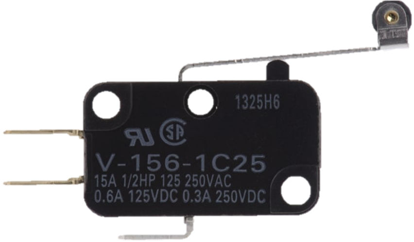
The V-156-1C25 is a miniature SPDT (Single Pole Double Throw) relay designed for low-power applications. Its compact design makes it ideal for switching small loads in various electronic circuits. This relay is widely used in automation systems, home appliances, and control circuits where reliable switching is required. Its versatility and durability make it a popular choice for both hobbyists and professionals.

Explore Projects Built with V-156-1C25

Use Cirkit Designer to design, explore, and prototype these projects online. Some projects support real-time simulation. Click "Open Project" to start designing instantly!
Aircraft Tow Release Control System with Dual Battery Backup
Image of Queen Air Tow Release Wiring: A project utilizing V-156-1C25 in a practical application
This circuit is designed for a tow release control system in an aircraft, featuring a P68 Tow Control Panel and a Tow Release With Switches assembly. The control panel receives power from two separate aircraft batteries, with one providing main power and the other serving as a backup. The Tow Release With Switches assembly is connected to the control panel, allowing for the actuation of the tow mechanism and providing feedback via an LED indicator.
Cirkit Designer LogoOpen Project in Cirkit Designer
Satellite-Based Timing and Navigation System with SDR and Atomic Clock Synchronization
Image of GPS 시스템 측정 구성도_Confirm: A project utilizing V-156-1C25 in a practical application
This circuit appears to be a complex system involving power supply management, GPS and timing synchronization, and data communication. It includes a SI-TEX G1 Satellite Compass for GPS data, an XHTF1021 Atomic Rubidium Clock for precise timing, and Ettus USRP B200 units for software-defined radio communication. Power is supplied through various SMPS units and distributed via terminal blocks and DC jacks. Data communication is facilitated by Beelink MINI S12 N95 computers, RS232 splitters, and a 1000BASE-T Media Converter for network connectivity. RF Directional Couplers are used to interface antennas with the USRP units, and the entire system is likely contained within cases for protection and organization.
Cirkit Designer LogoOpen Project in Cirkit Designer
Mega2560-Controlled Automation System with Non-Contact Liquid Level Sensing and Motor Control
Image of Project_AutomaticBartender: A project utilizing V-156-1C25 in a practical application
This circuit appears to be a complex control system centered around an Arduino Mega2560 R3 Pro microcontroller, which interfaces with multiple sensors (XKC-Y26-V non-contact liquid level sensors and an LM35 temperature sensor), servo motors, a touch display, and an IBT-2 H-Bridge motor driver for controlling a planetary gearbox motor. The system also includes a UART TTL to RS485 converter for communication, likely with the touch display, and a power management subsystem with a switching power supply, fuses, and circuit breakers for safety and voltage regulation (XL4016). The absence of embedded code suggests that the functionality of the microcontroller is not defined within the provided data.
Cirkit Designer LogoOpen Project in Cirkit Designer
Battery-Powered FPV Drone with Telemetry and Dual Motor Control
Image of Krul': A project utilizing V-156-1C25 in a practical application
This circuit appears to be a power distribution and control system for a vehicle with two motorized wheels, possibly a drone or a robot. It includes a lipo battery connected to a Power Distribution Board (PDB) that distributes power to two Electronic Speed Controllers (ESCs) which in turn control the speed and direction of the motors. The system also integrates a flight controller (H743-SLIM V3) for managing various peripherals including GPS, FPV camera system, and a telemetry link (ExpressLRS).
Cirkit Designer LogoOpen Project in Cirkit Designer

Explore Projects Built with V-156-1C25

Use Cirkit Designer to design, explore, and prototype these projects online. Some projects support real-time simulation. Click "Open Project" to start designing instantly!
Image of Queen Air Tow Release Wiring: A project utilizing V-156-1C25 in a practical application
Aircraft Tow Release Control System with Dual Battery Backup
This circuit is designed for a tow release control system in an aircraft, featuring a P68 Tow Control Panel and a Tow Release With Switches assembly. The control panel receives power from two separate aircraft batteries, with one providing main power and the other serving as a backup. The Tow Release With Switches assembly is connected to the control panel, allowing for the actuation of the tow mechanism and providing feedback via an LED indicator.
Cirkit Designer LogoOpen Project in Cirkit Designer
Image of GPS 시스템 측정 구성도_Confirm: A project utilizing V-156-1C25 in a practical application
Satellite-Based Timing and Navigation System with SDR and Atomic Clock Synchronization
This circuit appears to be a complex system involving power supply management, GPS and timing synchronization, and data communication. It includes a SI-TEX G1 Satellite Compass for GPS data, an XHTF1021 Atomic Rubidium Clock for precise timing, and Ettus USRP B200 units for software-defined radio communication. Power is supplied through various SMPS units and distributed via terminal blocks and DC jacks. Data communication is facilitated by Beelink MINI S12 N95 computers, RS232 splitters, and a 1000BASE-T Media Converter for network connectivity. RF Directional Couplers are used to interface antennas with the USRP units, and the entire system is likely contained within cases for protection and organization.
Cirkit Designer LogoOpen Project in Cirkit Designer
Image of Project_AutomaticBartender: A project utilizing V-156-1C25 in a practical application
Mega2560-Controlled Automation System with Non-Contact Liquid Level Sensing and Motor Control
This circuit appears to be a complex control system centered around an Arduino Mega2560 R3 Pro microcontroller, which interfaces with multiple sensors (XKC-Y26-V non-contact liquid level sensors and an LM35 temperature sensor), servo motors, a touch display, and an IBT-2 H-Bridge motor driver for controlling a planetary gearbox motor. The system also includes a UART TTL to RS485 converter for communication, likely with the touch display, and a power management subsystem with a switching power supply, fuses, and circuit breakers for safety and voltage regulation (XL4016). The absence of embedded code suggests that the functionality of the microcontroller is not defined within the provided data.
Cirkit Designer LogoOpen Project in Cirkit Designer
Image of Krul': A project utilizing V-156-1C25 in a practical application
Battery-Powered FPV Drone with Telemetry and Dual Motor Control
This circuit appears to be a power distribution and control system for a vehicle with two motorized wheels, possibly a drone or a robot. It includes a lipo battery connected to a Power Distribution Board (PDB) that distributes power to two Electronic Speed Controllers (ESCs) which in turn control the speed and direction of the motors. The system also integrates a flight controller (H743-SLIM V3) for managing various peripherals including GPS, FPV camera system, and a telemetry link (ExpressLRS).
Cirkit Designer LogoOpen Project in Cirkit Designer

Common Applications

  • Home automation systems
  • Industrial control panels
  • Signal switching in low-power circuits
  • DIY electronics projects
  • Robotics and mechatronics

Technical Specifications

Key Technical Details

Parameter Value
Contact Configuration SPDT (Single Pole Double Throw)
Rated Voltage 250V AC / 30V DC
Rated Current 15A
Contact Resistance ≤ 50 mΩ
Insulation Resistance ≥ 100 MΩ (at 500V DC)
Dielectric Strength 1500V AC for 1 minute
Operating Temperature -25°C to +85°C
Mechanical Life 10,000,000 operations
Electrical Life 100,000 operations
Dimensions 27.8mm x 10.3mm x 15.9mm

Pin Configuration and Descriptions

The V-156-1C25 relay has three pins for its SPDT configuration. The table below describes each pin:

Pin Name Description
Common (COM) The input terminal for the relay.
Normally Open (NO) The terminal that connects to COM when the relay is activated.
Normally Closed (NC) The terminal that connects to COM when the relay is not activated.

Usage Instructions

How to Use the V-156-1C25 in a Circuit

  1. Identify the Pins: Locate the COM, NO, and NC pins on the relay.
  2. Connect the Load:
    • Connect the load to the NO pin if you want it to be powered only when the relay is activated.
    • Connect the load to the NC pin if you want it to be powered when the relay is not activated.
  3. Power the Relay Coil: Apply the appropriate voltage to the relay coil to activate it. Ensure the voltage matches the relay's rated coil voltage.
  4. Control the Relay: Use a microcontroller, switch, or other control circuit to toggle the relay.

Important Considerations and Best Practices

  • Avoid Overloading: Ensure the load does not exceed the relay's rated current and voltage.
  • Use a Flyback Diode: When controlling the relay with a microcontroller, place a flyback diode across the relay coil to protect the circuit from voltage spikes.
  • Secure Connections: Use proper soldering or connectors to ensure reliable electrical connections.
  • Test the Circuit: Before deploying the relay in a critical application, test the circuit to ensure proper operation.

Example: Connecting the V-156-1C25 to an Arduino UNO

Below is an example of how to control the V-156-1C25 relay using an Arduino UNO:

// Define the pin connected to the relay
const int relayPin = 7;

void setup() {
  // Set the relay pin as an output
  pinMode(relayPin, OUTPUT);
}

void loop() {
  // Activate the relay
  digitalWrite(relayPin, HIGH);
  delay(1000); // Keep the relay on for 1 second

  // Deactivate the relay
  digitalWrite(relayPin, LOW);
  delay(1000); // Keep the relay off for 1 second
}

Note: Always use a transistor or relay driver circuit to interface the relay with the Arduino, as the Arduino's GPIO pins cannot directly supply the current required by the relay coil.

Troubleshooting and FAQs

Common Issues and Solutions

Issue Possible Cause Solution
Relay does not activate Insufficient voltage/current to the coil Check the power supply and ensure it matches the relay's rated coil voltage.
Load does not turn on/off Incorrect wiring of the load Verify the connections to the NO, NC, and COM pins.
Microcontroller resets when relay activates Voltage spike from the relay coil Add a flyback diode across the relay coil.
Relay heats up excessively Overloading the relay Ensure the load does not exceed the relay's rated current and voltage.

FAQs

  1. Can the V-156-1C25 be used with DC loads? Yes, the relay can switch DC loads up to 30V DC at 15A.

  2. What is the purpose of the flyback diode? The flyback diode protects the control circuit from voltage spikes generated when the relay coil is de-energized.

  3. Can I use the relay for high-frequency switching? No, the V-156-1C25 is not designed for high-frequency switching. It is best suited for low-speed applications.

  4. What happens if I exceed the rated current? Exceeding the rated current can damage the relay contacts and reduce its lifespan. Always operate within the specified limits.