
How to Use MAX485: Examples, Pinouts, and Specs
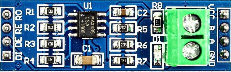
 Design with MAX485 in Cirkit Designer
Introduction
The MAX485 is a low-power, half-duplex RS-485 transceiver designed for reliable long-distance data transmission in noisy environments. Manufactured by Arduino, this component is ideal for multipoint communication on a bus, supporting data rates of up to 2.5 Mbps. Its robust design ensures minimal power consumption while maintaining high performance, making it suitable for industrial, commercial, and embedded systems.
Explore Projects Built with MAX485
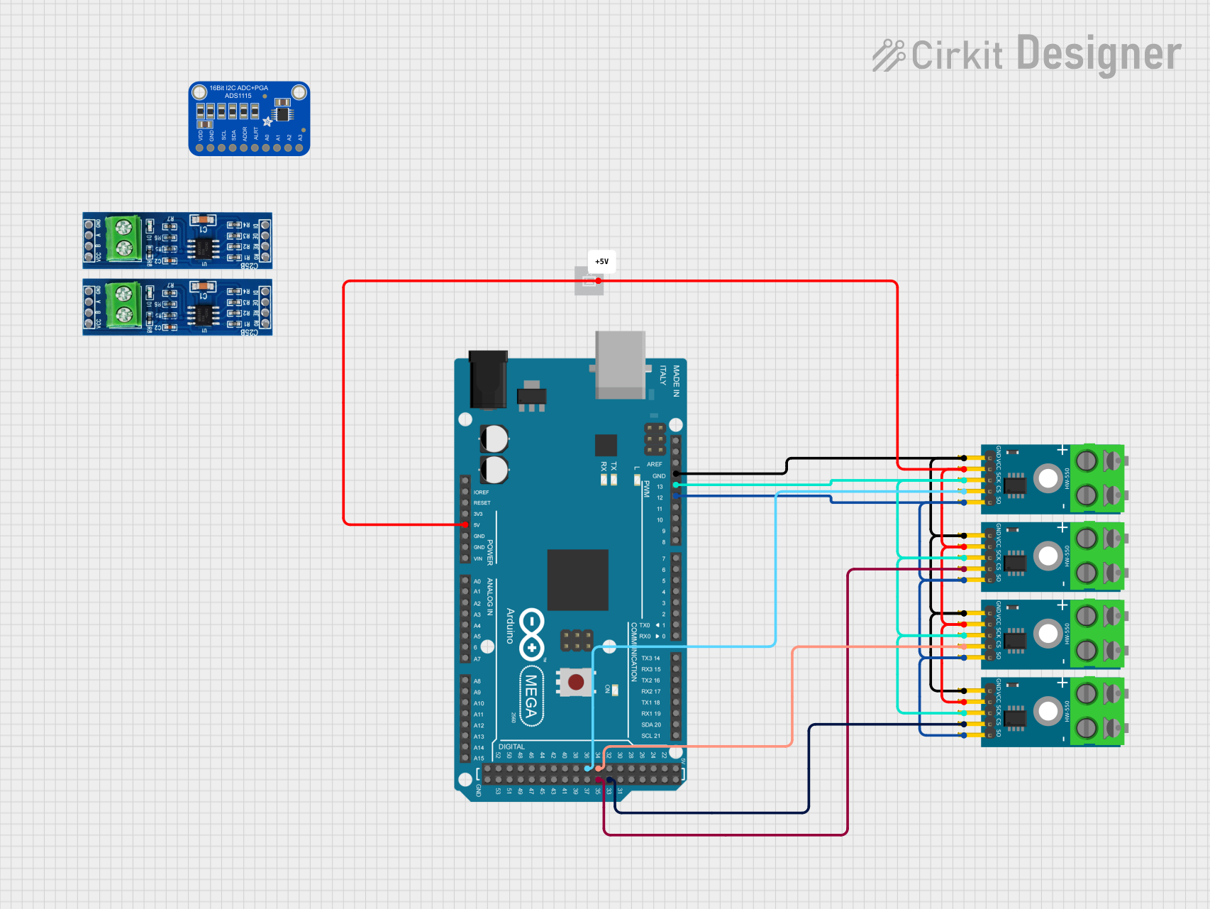 Open Project in Cirkit Designer
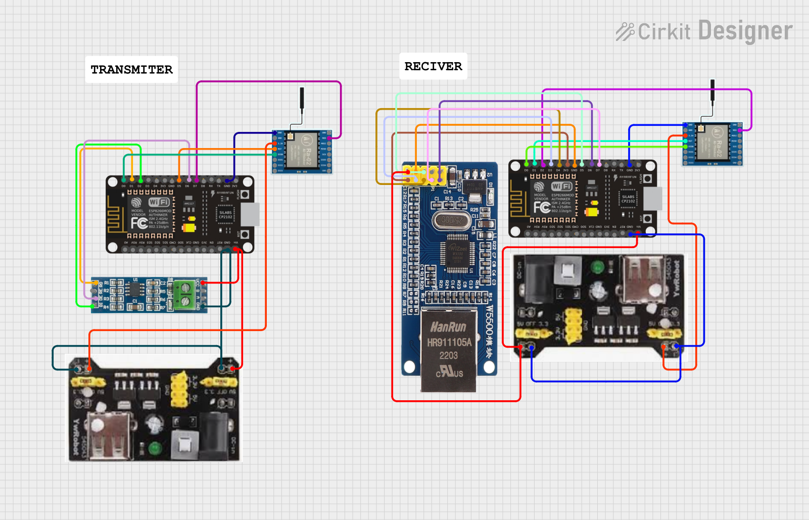 Open Project in Cirkit Designer
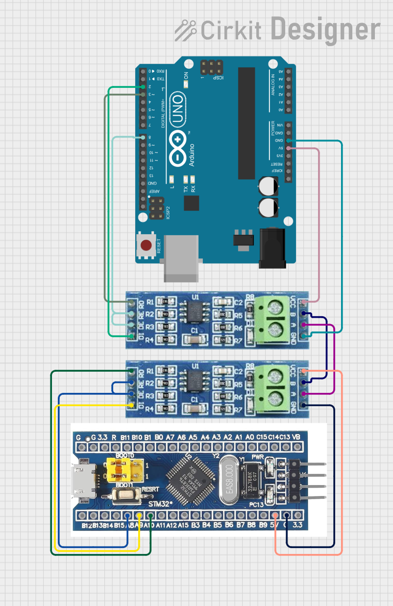 Open Project in Cirkit Designer
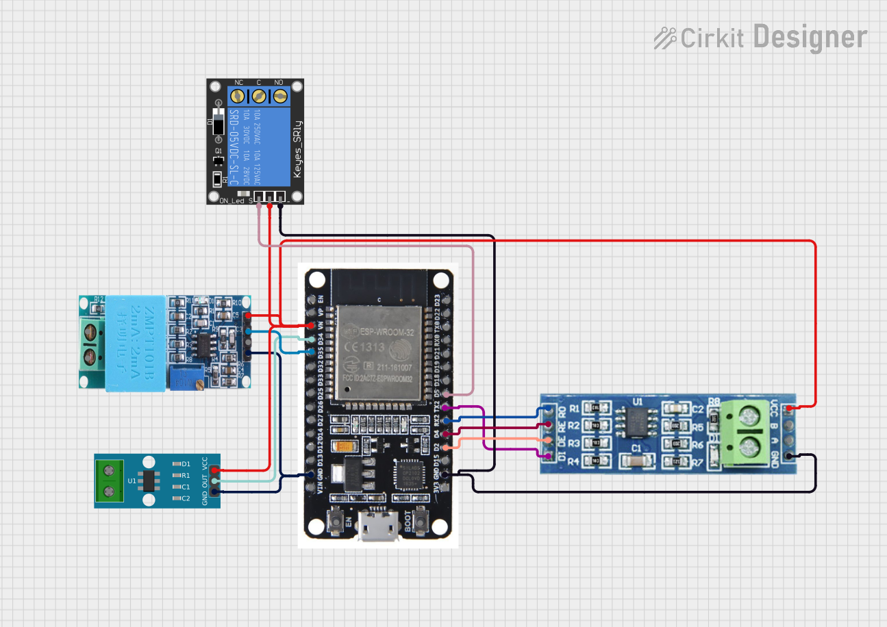 Open Project in Cirkit Designer
Explore Projects Built with MAX485
Open Project in Cirkit DesignerOpen Project in Cirkit DesignerOpen Project in Cirkit DesignerOpen Project in Cirkit DesignerCommon Applications and Use Cases
- Industrial automation and control systems
- Long-distance communication in noisy environments
- Multipoint data transmission on RS-485 buses
- Building automation (e.g., HVAC systems)
- Embedded systems requiring robust serial communication
Technical Specifications
The MAX485 transceiver is designed to meet the electrical characteristics of RS-485 and RS-422 standards. Below are its key technical details:
Key Specifications
| Parameter | Value |
|---|---|
| Supply Voltage (Vcc) | 4.75V to 5.25V |
| Data Rate | Up to 2.5 Mbps |
| Operating Temperature | -40°C to +85°C |
| Driver Output Voltage | -7V to +12V |
| Receiver Input Resistance | ≥ 12 kΩ |
| Low Power Shutdown Mode | 1 µA (typical) |
| Driver Short-Circuit Current | ±250 mA (maximum) |
| Communication Mode | Half-Duplex |
Pin Configuration and Descriptions
The MAX485 is an 8-pin IC with the following pinout:
| Pin No. | Pin Name | Description |
|---|---|---|
| 1 | RO | Receiver Output: Outputs the received data from the RS-485 bus. |
| 2 | RE̅ | Receiver Enable: Active-low input. Enables the receiver when low. |
| 3 | DE | Driver Enable: Active-high input. Enables the driver when high. |
| 4 | DI | Driver Input: Accepts data to be transmitted on the RS-485 bus. |
| 5 | GND | Ground: Connect to system ground. |
| 6 | A | Non-inverting Driver Output / Receiver Input (RS-485 bus line). |
| 7 | B | Inverting Driver Output / Receiver Input (RS-485 bus line). |
| 8 | Vcc | Power Supply: Connect to a 5V power source. |
Usage Instructions
The MAX485 is straightforward to use in RS-485 communication systems. Below are the steps and considerations for integrating it into your circuit.
Connecting the MAX485
- Power Supply: Connect the Vcc pin to a 5V power source and the GND pin to ground.
- RS-485 Bus Lines: Connect the A and B pins to the RS-485 bus. Use a twisted pair cable for optimal noise immunity.
- Driver and Receiver Control:
- To enable the driver, set the DE pin high.
- To enable the receiver, set the RE̅ pin low.
- For low-power shutdown mode, set both DE low and RE̅ high.
- Data Transmission:
- Send data to the DI pin for transmission on the RS-485 bus.
- Received data will be output on the RO pin.
Important Considerations
- Termination Resistors: Place a 120Ω termination resistor between the A and B lines at both ends of the RS-485 bus to prevent signal reflections.
- Biasing Resistors: Use pull-up and pull-down resistors on the A and B lines to ensure a known idle state when no device is driving the bus.
- Bus Length: The RS-485 standard supports cable lengths up to 1200 meters, but this depends on the data rate and cable quality.
- Device Count: The MAX485 supports up to 32 devices on the same bus.
Example: Using MAX485 with Arduino UNO
Below is an example of how to use the MAX485 with an Arduino UNO for RS-485 communication:
Circuit Connections
- Connect the MAX485's Vcc and GND to the Arduino's 5V and GND pins.
- Connect the DI pin to Arduino digital pin 3.
- Connect the RO pin to Arduino digital pin 2.
- Connect DE and RE̅ together and connect them to Arduino digital pin 4.
- Connect the A and B pins to the RS-485 bus.
Arduino Code
// RS-485 Communication Example with MAX485 and Arduino UNO

#define DE_RE 4  // Pin to control Driver Enable (DE) and Receiver Enable (RE̅)
#define DI 3     // Pin for Driver Input (DI)
#define RO 2     // Pin for Receiver Output (RO)

void setup() {
  pinMode(DE_RE, OUTPUT);  // Set DE/RE̅ pin as output
  pinMode(DI, OUTPUT);     // Set DI pin as output
  pinMode(RO, INPUT);      // Set RO pin as input

  digitalWrite(DE_RE, LOW);  // Enable receiver by default
  Serial.begin(9600);        // Initialize serial communication
}

void loop() {
  // Example: Sending data
  digitalWrite(DE_RE, HIGH);  // Enable driver
  digitalWrite(DI, HIGH);     // Send a HIGH signal
  delay(1000);                // Wait for 1 second
  digitalWrite(DI, LOW);      // Send a LOW signal
  delay(1000);                // Wait for 1 second

  // Example: Receiving data
  digitalWrite(DE_RE, LOW);   // Enable receiver
  if (digitalRead(RO) == HIGH) {
    Serial.println("Received HIGH signal");
  } else {
    Serial.println("Received LOW signal");
  }
}
Troubleshooting and FAQs
Common Issues and Solutions
No Communication on the Bus:
- Ensure the DE and RE̅ pins are correctly configured for transmission and reception.
- Verify the A and B lines are properly connected and terminated with 120Ω resistors.
Data Corruption:
- Check for proper biasing resistors on the A and B lines.
- Ensure the cable length and data rate are within RS-485 specifications.
Excessive Power Consumption:
- Verify that the device is not stuck in an active state. Use low-power shutdown mode when idle.
Signal Reflections:
- Confirm that termination resistors are installed at both ends of the RS-485 bus.
FAQs
Q: Can the MAX485 be used for full-duplex communication?
A: No, the MAX485 is a half-duplex transceiver. For full-duplex communication, consider using a full-duplex RS-485 transceiver like the MAX488.
Q: How many devices can I connect to the RS-485 bus?
A: The MAX485 supports up to 32 devices on the same bus.
Q: What is the maximum cable length supported by the MAX485?
A: The RS-485 standard supports cable lengths up to 1200 meters, but this depends on the data rate and cable quality.
Q: Can I use the MAX485 with a 3.3V microcontroller?
A: The MAX485 requires a 5V power supply. Use a level shifter to interface with 3.3V logic devices.