
How to Use Logic X0-1HN-EC: Examples, Pinouts, and Specs
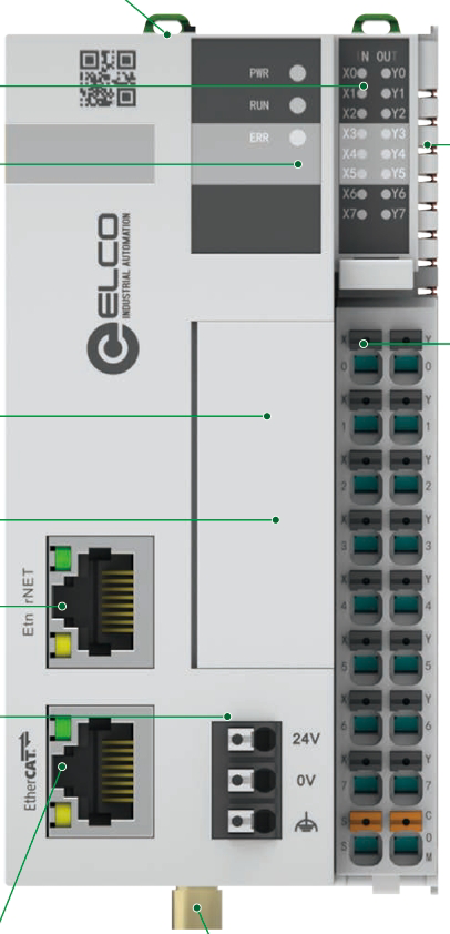
 Design with Logic X0-1HN-EC in Cirkit Designer
Introduction
The Logic X0-1HN-EC, manufactured by ELCO, is a high-performance logic gate designed for digital circuits. It offers fast switching speeds and low power consumption, making it an ideal choice for a wide range of electronic systems. This component is particularly suited for applications requiring reliable and efficient logic operations, such as signal processing, microcontroller interfacing, and digital system design.
Explore Projects Built with Logic X0-1HN-EC
 Open Project in Cirkit Designer
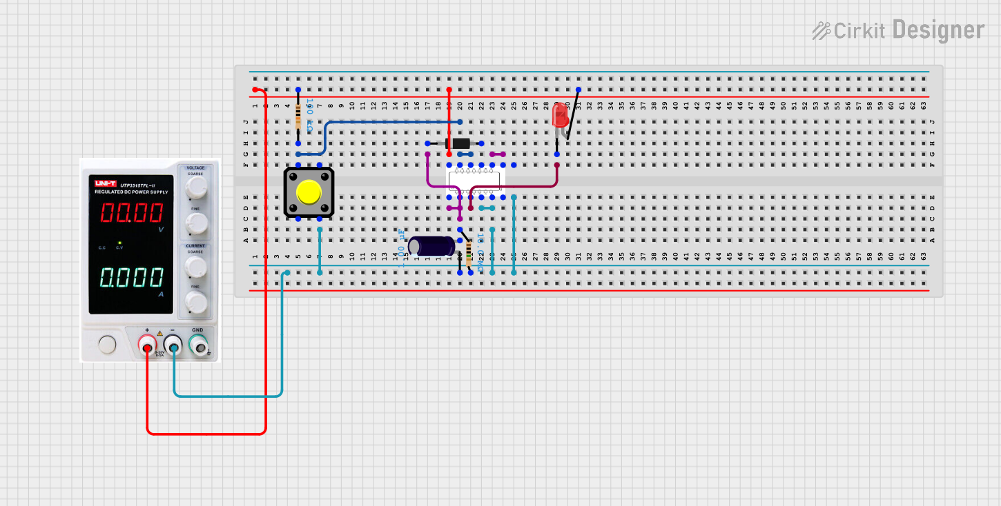 Open Project in Cirkit Designer
 Open Project in Cirkit Designer
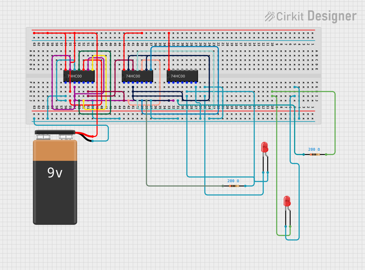 Open Project in Cirkit Designer
Explore Projects Built with Logic X0-1HN-EC
Open Project in Cirkit DesignerOpen Project in Cirkit DesignerOpen Project in Cirkit DesignerOpen Project in Cirkit DesignerCommon Applications:
- Digital signal processing
- Microcontroller and microprocessor interfacing
- Clock generation and synchronization
- Logic-level conversion
- General-purpose digital logic circuits
Technical Specifications
Key Technical Details:
| Parameter | Value |
|---|---|
| Supply Voltage (Vcc) | 2.0V to 5.5V |
| Input Voltage Range | 0V to Vcc |
| Output Voltage Range | 0V to Vcc |
| Maximum Input Current | ±1 µA |
| Propagation Delay | 3 ns (typical at 5V) |
| Output Current (Iout) | ±8 mA |
| Power Consumption | 0.1 mW (typical at 3.3V) |
| Operating Temperature | -40°C to +85°C |
| Package Type | SOT-23-5, SOIC-8 |
Pin Configuration and Descriptions:
SOT-23-5 Package:
| Pin Number | Name | Description |
|---|---|---|
| 1 | Vcc | Positive supply voltage |
| 2 | IN1 | Input 1 for the logic gate |
| 3 | IN2 | Input 2 for the logic gate |
| 4 | OUT | Output of the logic gate |
| 5 | GND | Ground (0V reference) |
SOIC-8 Package:
| Pin Number | Name | Description |
|---|---|---|
| 1 | Vcc | Positive supply voltage |
| 2 | IN1 | Input 1 for the logic gate |
| 3 | IN2 | Input 2 for the logic gate |
| 4 | NC | No connection |
| 5 | NC | No connection |
| 6 | OUT | Output of the logic gate |
| 7 | NC | No connection |
| 8 | GND | Ground (0V reference) |
Usage Instructions
How to Use the Logic X0-1HN-EC in a Circuit:
- Power Supply: Connect the Vcc pin to a stable power source within the range of 2.0V to 5.5V. Connect the GND pin to the ground of the circuit.
- Inputs: Apply digital signals (0V or Vcc) to the IN1 and IN2 pins. Ensure the input voltage levels are within the specified range.
- Output: The OUT pin will provide the logic operation result based on the input signals. Connect this pin to the desired load or circuit.
- Bypass Capacitor: Place a 0.1 µF ceramic capacitor close to the Vcc and GND pins to filter noise and ensure stable operation.
Important Considerations:
- Avoid exceeding the maximum voltage ratings to prevent damage to the component.
- Ensure proper grounding to minimize noise and interference.
- Use pull-up or pull-down resistors on unused input pins to avoid floating states.
- For high-speed applications, minimize trace lengths to reduce signal degradation.
Example: Connecting to an Arduino UNO
The Logic X0-1HN-EC can be used with an Arduino UNO to perform basic logic operations. Below is an example of using the component to implement an AND gate:
Circuit Connections:
- Connect the Vcc pin of the Logic X0-1HN-EC to the 5V pin of the Arduino.
- Connect the GND pin of the Logic X0-1HN-EC to the GND pin of the Arduino.
- Connect IN1 and IN2 to digital pins 2 and 3 of the Arduino, respectively.
- Connect the OUT pin to digital pin 4 of the Arduino.
Arduino Code:
// Define input and output pins
const int input1 = 2;  // Pin connected to IN1 of Logic X0-1HN-EC
const int input2 = 3;  // Pin connected to IN2 of Logic X0-1HN-EC
const int output = 4;  // Pin connected to OUT of Logic X0-1HN-EC

void setup() {
  // Initialize input pins as outputs to simulate logic signals
  pinMode(input1, OUTPUT);
  pinMode(input2, OUTPUT);

  // Initialize output pin as input to read the logic gate result
  pinMode(output, INPUT);

  // Start serial communication for debugging
  Serial.begin(9600);
}

void loop() {
  // Simulate logic inputs
  digitalWrite(input1, HIGH);  // Set IN1 to HIGH
  digitalWrite(input2, HIGH);  // Set IN2 to HIGH

  // Read the output of the logic gate
  int logicOutput = digitalRead(output);

  // Print the output to the Serial Monitor
  Serial.print("Logic Gate Output: ");
  Serial.println(logicOutput);

  delay(1000);  // Wait for 1 second
}
Troubleshooting and FAQs
Common Issues:
No Output Signal:
- Cause: Incorrect power supply or loose connections.
- Solution: Verify that Vcc and GND are properly connected and within the specified voltage range.
Floating Inputs:
- Cause: Unused input pins left unconnected.
- Solution: Use pull-up or pull-down resistors to define the state of unused inputs.
High Power Consumption:
- Cause: Excessive load on the output pin.
- Solution: Ensure the load connected to the OUT pin does not exceed the maximum output current rating.
Signal Distortion:
- Cause: Long trace lengths or noisy environment.
- Solution: Minimize trace lengths and use proper decoupling capacitors.
FAQs:
Can the Logic X0-1HN-EC operate at 1.8V?
- No, the minimum supply voltage is 2.0V. Operating below this voltage may result in unreliable performance.
What type of logic gate is implemented in this component?
- The Logic X0-1HN-EC is a configurable logic gate. Refer to the datasheet for specific configurations.
Is the component suitable for high-speed applications?
- Yes, with a typical propagation delay of 3 ns at 5V, it is well-suited for high-speed digital circuits.
Can I use this component with 3.3V systems?
- Yes, the Logic X0-1HN-EC is compatible with 3.3V logic levels.
By following this documentation, users can effectively integrate the Logic X0-1HN-EC into their digital circuits and troubleshoot common issues with ease.