
How to Use JGA25-371dc motor with encoder: Examples, Pinouts, and Specs
 Design with JGA25-371dc motor with encoder in Cirkit Designer
Introduction
The JGA25-371 DC motor with encoder is a compact and versatile motor designed for applications requiring precise control of speed and position. This motor integrates an encoder, which provides feedback on the motor's rotational position and speed, making it ideal for robotics, automation systems, and other projects where accuracy and control are critical. Its small size and high torque make it suitable for a wide range of applications, from hobbyist projects to industrial automation.
Explore Projects Built with JGA25-371dc motor with encoder
 Open Project in Cirkit Designer
 Open Project in Cirkit Designer
 Open Project in Cirkit Designer
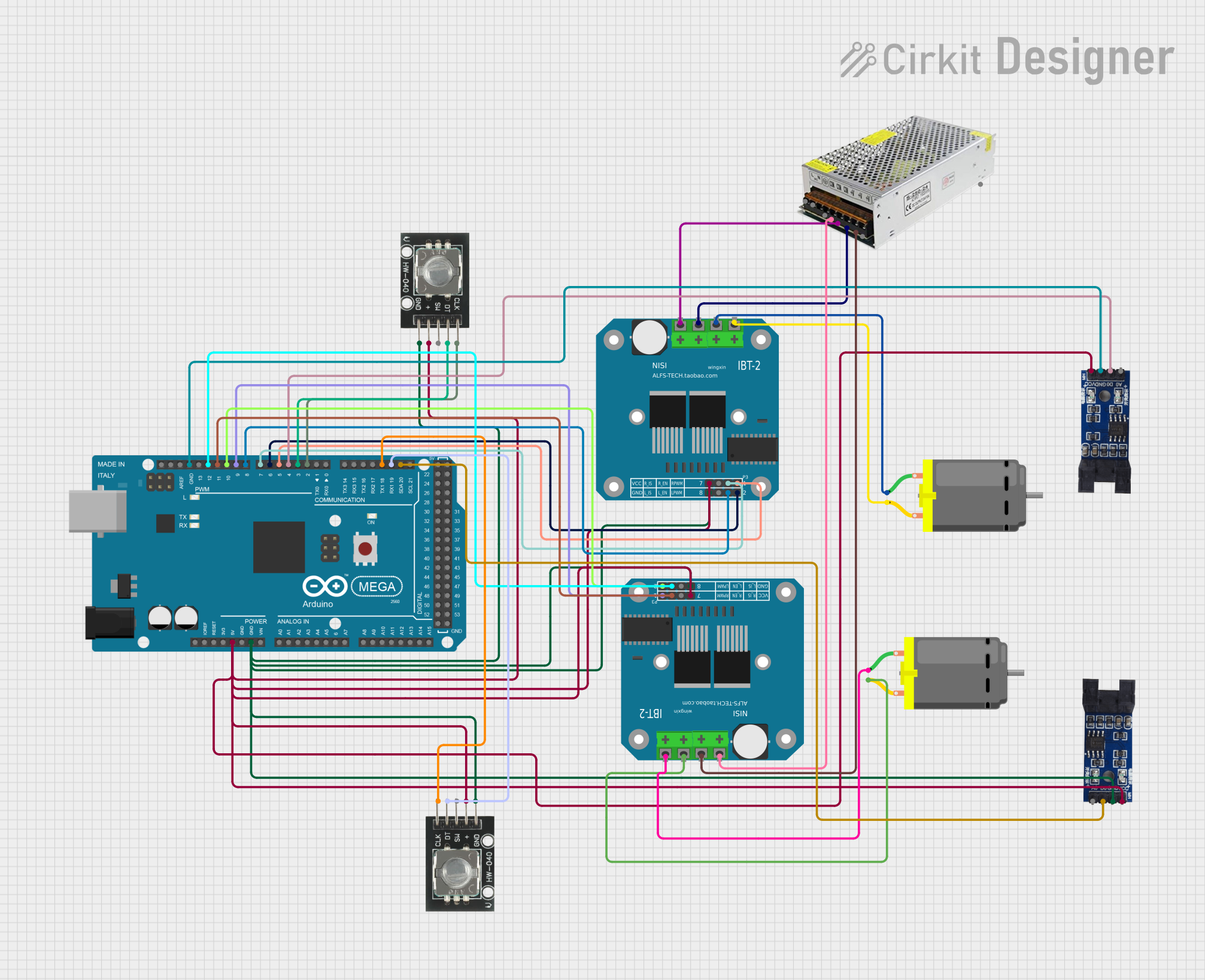 Open Project in Cirkit Designer
Explore Projects Built with JGA25-371dc motor with encoder
Open Project in Cirkit DesignerOpen Project in Cirkit DesignerOpen Project in Cirkit DesignerOpen Project in Cirkit DesignerCommon Applications
- Robotic arms and mobile robots
- Automated conveyor systems
- Precision control systems
- DIY electronics and hobby projects
- Motorized camera sliders and gimbals
Technical Specifications
Below are the key technical details of the JGA25-371 DC motor with encoder:
| Parameter | Value |
|---|---|
| Operating Voltage | 6V to 12V |
| Rated Torque | 1.5 kg·cm (at 12V) |
| No-Load Speed | 100 RPM to 600 RPM (varies by model) |
| Gear Ratio | 1:37 |
| Encoder Type | Hall-effect quadrature encoder |
| Encoder Resolution | 11 pulses per revolution (PPR) |
| Shaft Diameter | 4 mm |
| Motor Dimensions | 25 mm (diameter) × 37 mm (length) |
| Current Consumption | 100 mA (no load), up to 1.2 A (stall) |
| Weight | ~100 g |
Pin Configuration
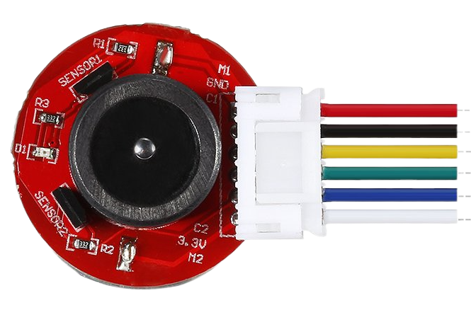
The JGA25-371 motor with encoder typically has a 6-pin connector. The pinout is as follows:
| Pin | Function | Description |
|---|---|---|
| 1 | Motor Power (+) | Positive terminal for motor power supply |
| 2 | Motor Power (-) | Negative terminal for motor power supply |
| 3 | Encoder VCC | Power supply for the encoder (3.3V or 5V) |
| 4 | Encoder GND | Ground for the encoder |
| 5 | Encoder A (Signal) | Quadrature encoder channel A output |
| 6 | Encoder B (Signal) | Quadrature encoder channel B output |
Usage Instructions
Connecting the Motor
- Power Supply: Connect the motor power pins (Pin 1 and Pin 2) to a DC power source. Ensure the voltage matches the motor's operating range (6V to 12V).
- Encoder Connections:
- Connect the encoder VCC (Pin 3) to a 3.3V or 5V power source, depending on your microcontroller's logic level.
- Connect the encoder GND (Pin 4) to the ground of your circuit.
- Connect Encoder A (Pin 5) and Encoder B (Pin 6) to the digital input pins of your microcontroller.
Using with an Arduino UNO
Below is an example of how to use the JGA25-371 motor with encoder in an Arduino UNO project. This code reads the encoder signals to calculate the motor's speed and direction.
// Define encoder pins
const int encoderA = 2; // Connect Encoder A to Arduino pin 2
const int encoderB = 3; // Connect Encoder B to Arduino pin 3

volatile int encoderPosition = 0; // Tracks the encoder position
int lastEncoded = 0; // Stores the last encoder state

void setup() {
  pinMode(encoderA, INPUT_PULLUP); // Set Encoder A as input with pull-up
  pinMode(encoderB, INPUT_PULLUP); // Set Encoder B as input with pull-up

  // Attach interrupts to encoder pins
  attachInterrupt(digitalPinToInterrupt(encoderA), updateEncoder, CHANGE);
  attachInterrupt(digitalPinToInterrupt(encoderB), updateEncoder, CHANGE);

  Serial.begin(9600); // Initialize serial communication
}

void loop() {
  // Print the encoder position to the Serial Monitor
  Serial.print("Encoder Position: ");
  Serial.println(encoderPosition);
  delay(100); // Small delay for readability
}

// Interrupt service routine to update encoder position
void updateEncoder() {
  int MSB = digitalRead(encoderA); // Most significant bit
  int LSB = digitalRead(encoderB); // Least significant bit

  int encoded = (MSB << 1) | LSB; // Combine MSB and LSB into a single value
  int sum = (lastEncoded << 2) | encoded; // Combine previous and current states

  // Determine direction based on state transitions
  if (sum == 0b1101 || sum == 0b0100 || sum == 0b0010 || sum == 0b1011) {
    encoderPosition++;
  } else if (sum == 0b1110 || sum == 0b0111 || sum == 0b0001 || sum == 0b1000) {
    encoderPosition--;
  }

  lastEncoded = encoded; // Update the last encoded state
}
Important Considerations
- Power Supply: Ensure the motor is powered within its specified voltage range to avoid damage.
- Current Handling: Use a motor driver or H-bridge circuit to control the motor, as the Arduino cannot supply sufficient current directly.
- Debouncing: Encoder signals may require debouncing or filtering to ensure accurate readings.
- Mounting: Secure the motor properly to prevent vibrations that could affect encoder readings.
Troubleshooting and FAQs
Common Issues
Motor Not Spinning
- Cause: Insufficient power supply or incorrect wiring.
- Solution: Verify the power supply voltage and check all connections.
Encoder Not Providing Feedback
- Cause: Incorrect encoder wiring or incompatible voltage levels.
- Solution: Ensure the encoder VCC matches the microcontroller's logic level (3.3V or 5V).
Inaccurate Encoder Readings
- Cause: Noise or signal interference.
- Solution: Use shielded cables for encoder connections and implement software debouncing.
Motor Overheating
- Cause: Prolonged operation at high current or stall conditions.
- Solution: Avoid stalling the motor and ensure proper ventilation.
FAQs
Q: Can I use the JGA25-371 motor with a 3.3V microcontroller?
A: Yes, but ensure the encoder VCC is connected to 3.3V, and use a motor driver compatible with 3.3V logic.
Q: How do I reverse the motor's direction?
A: Swap the connections of the motor power pins (Pin 1 and Pin 2) or use an H-bridge motor driver.
Q: What is the purpose of the encoder?
A: The encoder provides feedback on the motor's position and speed, enabling precise control in applications like robotics and automation.
Q: Can I control the motor speed with PWM?
A: Yes, use a motor driver that supports PWM (Pulse Width Modulation) to control the motor's speed.
This documentation provides a comprehensive guide to using the JGA25-371 DC motor with encoder, ensuring successful integration into your projects.