How to Use L298P drive shield: Examples, Pinouts, and Specs
Introduction
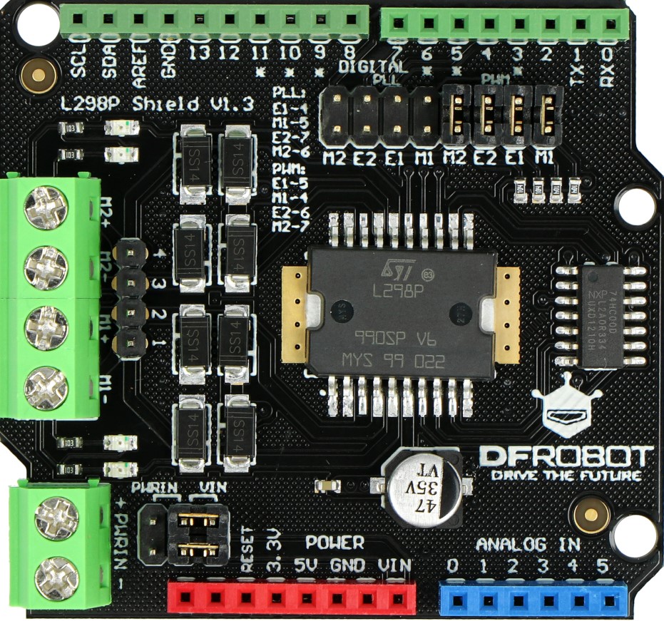
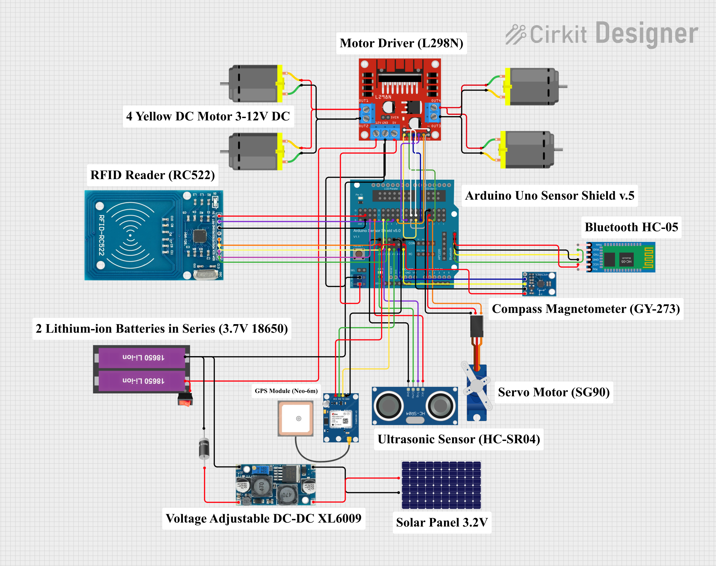
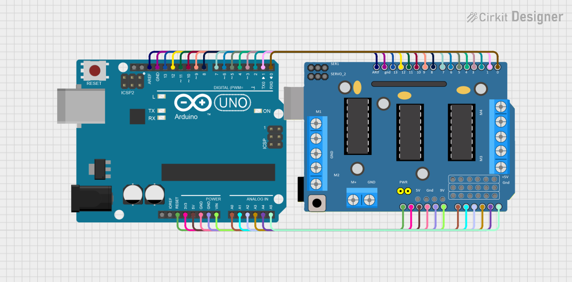
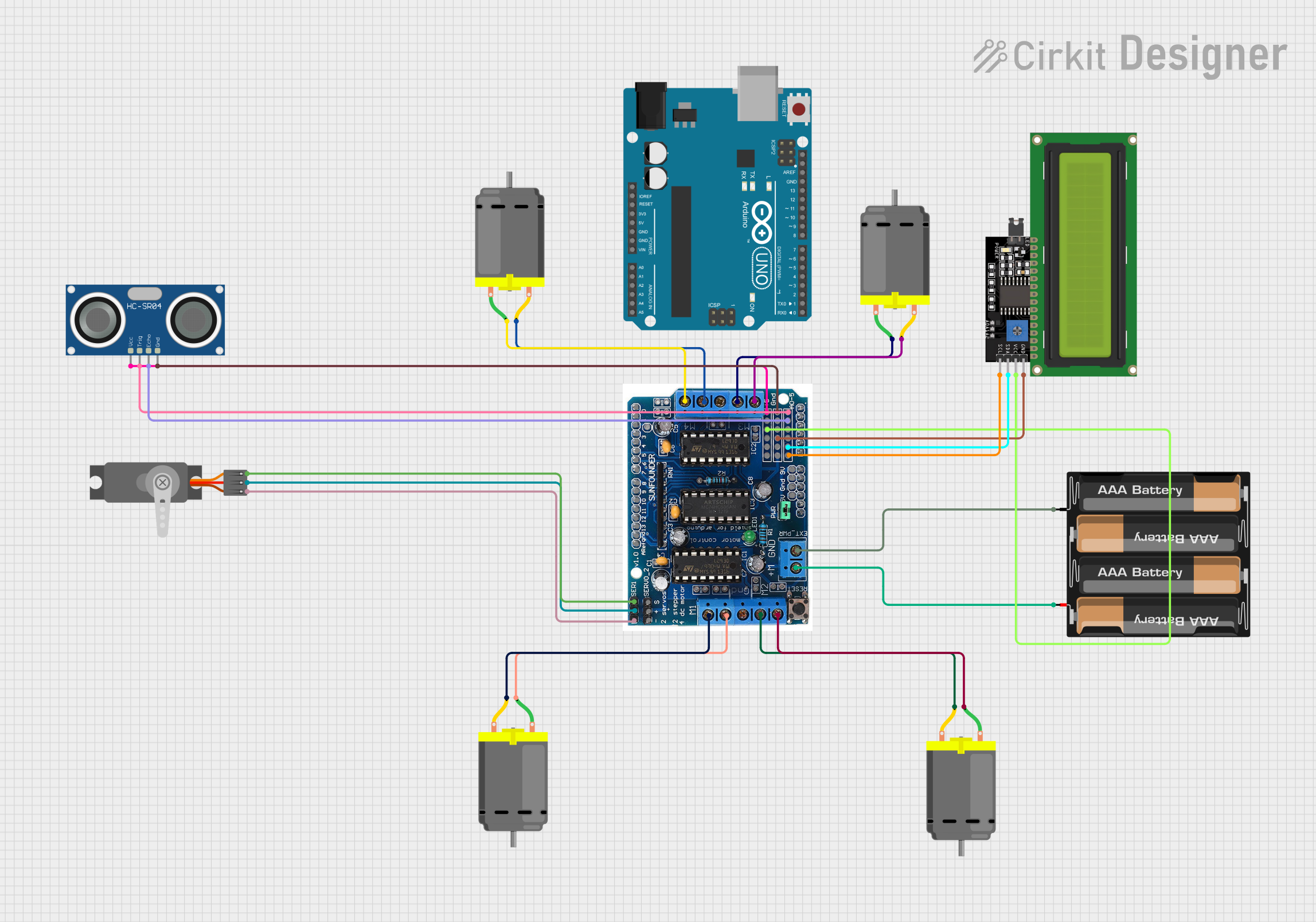
The L298P Drive Shield is a versatile motor driver shield designed for use with the Arduino platform. It is based on the L298P motor driver IC which allows for the control of two DC motors or one stepper motor. The shield is capable of driving motors with a voltage range typically from 5V to 12V, making it suitable for a wide array of robotics and DIY projects.
Explore Projects Built with L298P drive shield

Explore Projects Built with L298P drive shield
Common Applications and Use Cases
- Robotics: Driving wheels or tracks on a robot.
- CNC machines: Controlling stepper motors for precise movements.
- Home automation: Operating motorized curtains, blinds, or doors.
- Educational projects: Teaching motor control principles.
Technical Specifications
Key Technical Details
- Motor supply: 5V to 12V
- Logic supply: 5V from Arduino board
- Maximum current: 2A per channel
- Peak current: Up to 3A for short pulses
- Control signal input voltage: 2.3V to VSS
Pin Configuration and Descriptions
| Pin Number | Function | Description |
|---|---|---|
| 1 | ENA | Enables PWM signal for Motor A |
| 2 | IN1 | Control pin for Motor A direction |
| 3 | IN2 | Control pin for Motor A direction |
| 4 | ENB | Enables PWM signal for Motor B |
| 5 | IN3 | Control pin for Motor B direction |
| 6 | IN4 | Control pin for Motor B direction |
| 7 | +5V | Regulated 5V output (if jumper is in place) |
| 8 | GND | Ground |
| 9 | +12V (Vin) | Motor power supply input (5V to 12V) |
Usage Instructions
How to Use the Component in a Circuit
Power Connections:
- Connect the motor supply voltage (5V to 12V) to the Vin pin.
- Ensure the Arduino board is powered, which will also power the logic part of the shield.
Motor Connections:
- Connect your DC motors to the Motor A and Motor B output terminals.
- For a stepper motor, connect the coils to the Motor A and Motor B terminals accordingly.
Control Connections:
- The ENA and ENB pins are used to enable the motors and control their speed through PWM.
- The IN1, IN2, IN3, and IN4 pins are used to set the direction of the motors.
Important Considerations and Best Practices
- Always ensure that the power supply voltage and current do not exceed the shield's ratings.
- Use PWM signals on ENA and ENB for speed control.
- Make sure the motors are not drawing more current than the shield can handle.
- Disconnect the power supply before making or changing connections to prevent damage.
Example Code for Arduino UNO
#include <Arduino.h>

// Motor A
int ENA = 5; // Speed control
int IN1 = 2; // Direction
int IN2 = 3; // Direction

// Motor B
int ENB = 6; // Speed control
int IN3 = 4; // Direction
int IN4 = 7; // Direction

void setup() {
  // Set all the motor control pins to outputs
  pinMode(ENA, OUTPUT);
  pinMode(IN1, OUTPUT);
  pinMode(IN2, OUTPUT);
  pinMode(ENB, OUTPUT);
  pinMode(IN3, OUTPUT);
  pinMode(IN4, OUTPUT);
}

void loop() {
  // Drive Motor A forward at full speed
  digitalWrite(IN1, HIGH);
  digitalWrite(IN2, LOW);
  analogWrite(ENA, 255); // Set speed to maximum (PWM value 0 to 255)

  // Drive Motor B backward at half speed
  digitalWrite(IN3, LOW);
  digitalWrite(IN4, HIGH);
  analogWrite(ENB, 127); // Set speed to half of maximum

  delay(2000); // Run motors for 2 seconds

  // Stop both motors
  digitalWrite(IN1, LOW);
  digitalWrite(IN2, LOW);
  digitalWrite(IN3, LOW);
  digitalWrite(IN4, LOW);
  analogWrite(ENA, 0); // Set speed to zero
  analogWrite(ENB, 0); // Set speed to zero

  delay(1000); // Wait for 1 second
}
Troubleshooting and FAQs
Common Issues Users Might Face
- Motors not running: Check power supply and connections. Ensure the jumper on the shield is in place if you are using the onboard 5V regulator.
- Motors running weakly: Ensure the power supply can deliver enough current. Check for loose connections.
- Overheating: If the shield or motors are overheating, reduce the load or duty cycle.
Solutions and Tips for Troubleshooting
- Always start with a simple test code to ensure basic functionality.
- Use a multimeter to check for proper voltage levels at the motor outputs.
- If using PWM, start with low duty cycle values and increase gradually.
FAQs
Q: Can I control a stepper motor with this shield? A: Yes, the L298P Drive Shield can control a bipolar stepper motor using the Motor A and Motor B connections.
Q: What is the maximum current the shield can handle? A: The shield can handle up to 2A per channel continuously, with peak currents of up to 3A for short pulses.
Q: Can I use this shield with other microcontrollers besides Arduino? A: Yes, as long as the microcontroller provides compatible logic voltage levels and can generate PWM signals.