
How to Use dmx out 5 pin: Examples, Pinouts, and Specs
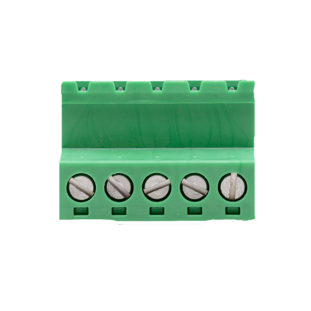
 Design with dmx out 5 pin in Cirkit Designer
Introduction
The DMX Out 5-Pin Connector is a standardized interface used for DMX512 communication, a protocol widely employed in stage lighting and entertainment systems. This connector facilitates the transmission of digital control signals from a DMX controller to lighting fixtures, dimmers, or other DMX-compatible devices. Its robust design and reliable performance make it a staple in professional lighting setups.
Explore Projects Built with dmx out 5 pin
 Open Project in Cirkit Designer
 Open Project in Cirkit Designer
 Open Project in Cirkit Designer
 Open Project in Cirkit Designer
Explore Projects Built with dmx out 5 pin
Open Project in Cirkit DesignerOpen Project in Cirkit DesignerOpen Project in Cirkit DesignerOpen Project in Cirkit DesignerCommon Applications and Use Cases
- Stage lighting control in theaters, concerts, and live events
- Architectural lighting systems
- Club and DJ lighting setups
- Integration with DMX-controlled fog machines, lasers, and moving heads
- Data transmission in multi-fixture lighting networks
Technical Specifications
The DMX Out 5-Pin Connector adheres to the DMX512 standard, ensuring compatibility with a wide range of devices. Below are the key technical details:
General Specifications
- Connector Type: 5-pin XLR (male or female, depending on application)
- Protocol Supported: DMX512 (Digital Multiplex)
- Voltage Rating: 0-5V (digital signal)
- Current Rating: Typically less than 1A
- Material: Metal housing with gold-plated or silver-plated pins for durability
- Cable Compatibility: Shielded twisted-pair cables (120-ohm impedance)
Pin Configuration and Descriptions
The DMX Out 5-Pin Connector uses the following pinout:
| Pin Number | Signal Name | Description |
|---|---|---|
| 1 | Ground (Shield) | Common ground for the DMX signal and shielding for noise reduction. |
| 2 | Data- (Negative) | Inverted (negative) DMX data signal. |
| 3 | Data+ (Positive) | Non-inverted (positive) DMX data signal. |
| 4 | Optional Data- | Reserved for future use or secondary data link (not commonly used). |
| 5 | Optional Data+ | Reserved for future use or secondary data link (not commonly used). |
Note: Pins 4 and 5 are rarely used in most DMX512 applications. For standard setups, only pins 1, 2, and 3 are typically connected.
Usage Instructions
How to Use the DMX Out 5-Pin Connector in a Circuit
- Connect the DMX Controller: Plug the DMX Out 5-Pin Connector into the DMX output port of your controller.
- Connect to Fixtures: Use a shielded twisted-pair DMX cable to link the connector to the DMX input of the first lighting fixture.
- Daisy-Chaining Fixtures: Continue connecting additional fixtures in a daisy-chain configuration, ensuring the last fixture in the chain has a DMX terminator (120-ohm resistor) installed.
- Verify Connections: Ensure all connections are secure and that the cable shielding is properly grounded to avoid signal interference.
Important Considerations and Best Practices
- Cable Length: The maximum recommended cable length for DMX512 is 300 meters (984 feet). Exceeding this may cause signal degradation.
- Termination: Always terminate the DMX line with a 120-ohm resistor at the last fixture to prevent signal reflections.
- Avoid Y-Splitters: Use proper DMX splitters for branching connections instead of Y-splitters, which can cause signal issues.
- Shielding: Use shielded cables to minimize electromagnetic interference (EMI).
- Pin Compatibility: Ensure that the connected devices use the same pinout standard (5-pin DMX vs. 3-pin DMX).
Example: Connecting to an Arduino UNO
The DMX Out 5-Pin Connector can be interfaced with an Arduino UNO using a DMX shield or transceiver IC (e.g., MAX485). Below is an example code snippet for sending DMX data:
#include <DMXSerial.h> // Include the DMXSerial library

void setup() {
  DMXSerial.init(DMXController); // Initialize as DMX controller
  DMXSerial.write(1, 255);       // Set channel 1 to maximum brightness
  DMXSerial.write(2, 128);       // Set channel 2 to 50% brightness
}

void loop() {
  // Continuously send DMX data
  DMXSerial.update();
}
Note: Use a DMX shield or transceiver IC to convert the Arduino's TTL signals to RS-485, which is required for DMX communication.
Troubleshooting and FAQs
Common Issues and Solutions
No Signal Detected by Fixtures:
- Verify that the DMX Out 5-Pin Connector is securely plugged into the controller.
- Check the cable for damage or loose connections.
- Ensure the DMX terminator is installed at the end of the chain.
Flickering Lights:
- Inspect the cable shielding and grounding to reduce interference.
- Ensure the cable length does not exceed the DMX512 standard limit.
- Replace the DMX cable if it is of poor quality or damaged.
Inconsistent Behavior Across Fixtures:
- Confirm that each fixture has a unique DMX address.
- Check for proper daisy-chaining and avoid using Y-splitters.
Pins 4 and 5 Not Working:
- Pins 4 and 5 are reserved for future use or secondary data links. Most devices do not utilize these pins.
FAQs
Q: Can I use a 3-pin DMX cable with a 5-pin DMX connector?
A: Yes, with an appropriate adapter. However, ensure that only pins 1, 2, and 3 are connected, as pins 4 and 5 are not used in most setups.
Q: What happens if I don’t use a DMX terminator?
A: Without a terminator, signal reflections may occur, causing flickering or erratic behavior in fixtures.
Q: Can I use regular microphone cables for DMX?
A: It is not recommended. DMX requires shielded twisted-pair cables with 120-ohm impedance for reliable communication.
Q: How do I test if the DMX Out 5-Pin Connector is working?
A: Use a DMX tester or connect it to a known working fixture. Verify that the fixture responds to DMX signals as expected.
By following this documentation, you can effectively use the DMX Out 5-Pin Connector in your lighting control systems with confidence and reliability.